CM-150 CA Product Guide 11
Prepare for Cable Connections
Surface Mount Installation
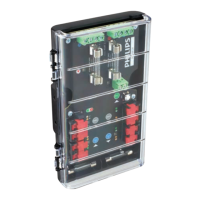
1. Using the included 2.5 mm (1/4 in) hex wrench, loosen the housing cover’s six
captive screws to open the CM-150 CA housing.
1/4 in hex
2. Loosen the cable glands.
Make Data Input Connections
Instead of RJ45 connectors, CM-150 CA uses double-pair, double-entry IDC
connectors, which accept unstripped cable wire strands.
Surface Mount Installation
1. Run Cat. 5e or better cable from the data output port of a Philips Color Kinetics
Ethernet controller, such as Light System Manager or Video System Manager Pro.
2. If necessary, cut the cable jacket to expose the wire pairs. Do not strip the wire
pairs. The Brown, Brown/White, Blue, and Blue/White wires are not used and
should be capped and turned back.
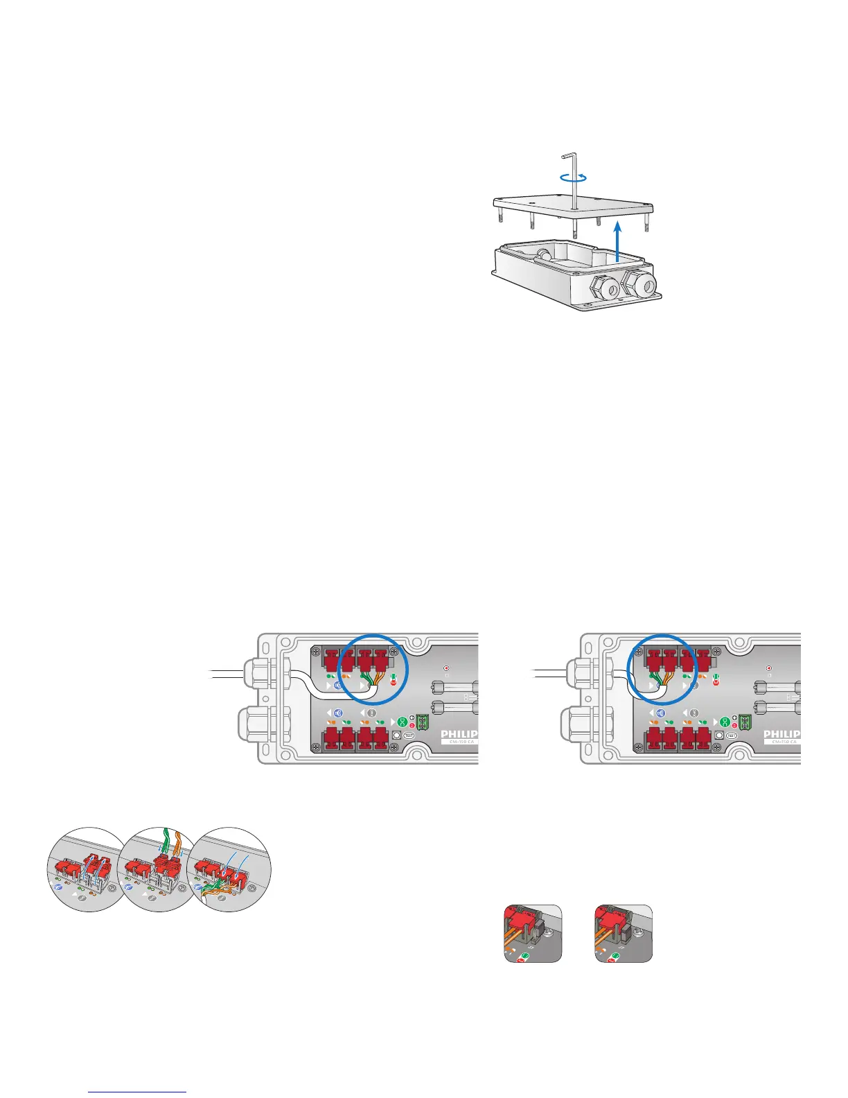
3. Locate the pivot connectors inside the CM-150 CA housing. If installing in a
DMX environment, open the DMX input connectors. If installing in an Ethernet
environment, open the Ethernet input connectors.
4. Feed the data cable through the smaller cable gland. Following the wire color
codes printed on the data board, insert the Orange/White, Orange, Green/White,
and Green wires into the pivot connector’s wire entry holes.
5. While holding the wires rmly in place, push down on the pivot connectors until
they click shut.
3. If installing CM-150 CA in a DMX installation, terminate the DMX run.
Not terminated Terminated
E IDC connectors accept wire sizes from
0.326 to 0.129 mm
2
(22 to 26 AWG).