Chapter 3
3-6 Respironics V60 Ventilator User Manual 1047358 Rev N
General information
Ventilator unit
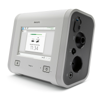
Figure 3-3 through Figure 3-5 show the controls, indicators, and other
important parts of the ventilator unit.
Figure 3-3: Front view
Number Description
1 Graphical user interface. Color LCD (liquid crystal display) with touchscreen.
2 Navigation ring. Lets you adjust values and navigate the graphical user interface
by rotating the finger on its touchpad.
3 Accept button. Activates selections.
4 Proximal pressure port. Connection for tubing that monitors patient pressure in
the patient circuit.
5 Ventilator outlet (To patient) port. Main connection for the patient circuit.
Delivers air and oxygen in prescribed pressures to the patient.
6 Alarm speakers (beneath ventilator)
7 Alarm LED. Flashes during a high-priority alarm. On continuously during a
ventilator inoperative condition.
8 Battery (charged) LED. Flashes when battery is charging. On continuously when
battery is charged. Off when ventilator is running on battery or when the
ventilator is off and AC power is not connected.
9 ON/Shutdown key with LED. Turns on AC power and initiates ventilator shutdown.
LED is continuously on when AC power is connected.

 Loading...