Mechanical Instructions
EN 9LCD CMO 2K7 4.
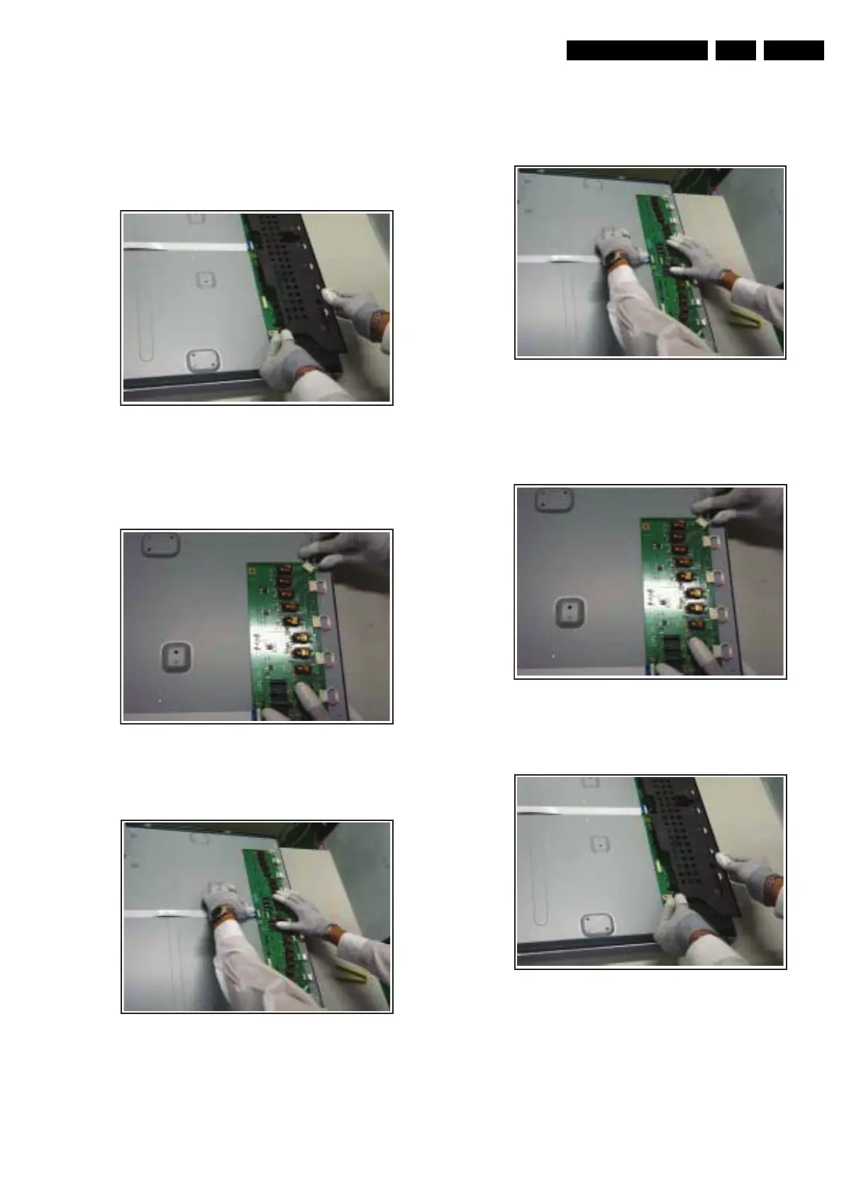
4.3.2 Inverter Board
Disassembly
1. Place the panel on the foam bars, and remove the screws
of the inverter cover (the number of screws depends on the
model).
2. Remove the inverter cover in the direction as shown.
Figure 4-21 Remove connectors
3. Remove the connectors attached to the inverter. Start at
the top, and be careful not to pull and drag the wires. Use
tweezers if necessary.
Figure 4-22 Remove connectors
4. Release the FFC from its connector.
Figure 4-23 Remove FFC
5. Remove the Inverter Board.
Reassembly
1. Place the panel on the foam bars, and place the Inverter
Board on the panel via the alignment pins.
2. Insert and lock the FFC into its connector.
Figure 4-24 FFC insertion
3. Insert the lamp connectors. Be sure to place the round spot
upwards. Important: Connectors should be well
connected, to avoid electrical sparks!
Figure 4-25 Insert lamp connectors
4. Place the inverter cover and secure the cover screws.
Figure 4-26 Place cover
5. Assembly completed. Check lamp functioning.
H_16920_031.eps
101007
H_16920_032.eps
101007
H_16920_033.eps
101007
H_16920_033.eps
101007
H_16920_032.eps
101007
H_16920_031.eps
101007
 Loading...