ILLUSTRATED PARTS BREAKDOWN :
3
02.9663.0010 F 14-May-2009 111
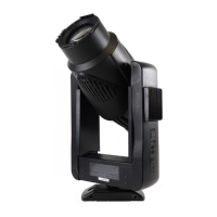
Tilt Motor Assembly (continued)
Figure 3-32: Tilt Motor Assembly
1
2
3
4
7 (x2)
9 (x4)
8 (x4)
5 (x4)
6 (x4)
0.226"
2
1
3
Step 1. Apply one drop of Loctite 603 to motor shaft.
Step 2. Install drive pulley on motor shaft using twisting
motion to insure coverage of shaft with loctite.
Step 3. Do not allow Loctite to drip into motor bearing.
Step 4. Set pulley height as shown above.
Step 5. Apply Loctite 242 to pulley set screws. Insure
set screws are aligned and tightened on flat
sides of motor shaft.
Pulley Height Detail & Installation
Note: Vari-Lite recommends that this assembly be replaced
as a complete assembly. Although you can replace only the
motor, the pulley (Item 2) is bonded to the motor shaft during
assembly and cannot be removed intact. If you order a
replacement motor (Item 4), also order the pulley (Item 2).
Contact Vari-Lite Customer Service for installation information.
 Loading...