MAINTENANCE :
2
02.9663.0010 F 14-May-2009 43
Ignitor PCB Replacement
Note: This procedure not applicable to all units.
Parts:
PCB ASSEMBLY, IGNITOR (24.9661.3126)
Tools:
#2 Phillips screwdriver
To remove and replace ignitor PCB:
Step 1. Disconnect luminaire AC input cable from power source.
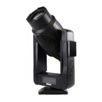
Step 2. Remove yoke leg cover (side without menu display) by removing four 6-
32x3/8" PTB screws as shown in Figure 2-21.
Step 3. At ignitor PCB, disconnect lamp connectors.
Step 4. Remove four 6-32x3/8" PPB screws and remove ignitor PCB.
Step 5. Replace ignitor PCB by doing steps 2 through 4 in reverse.
Figure 2-21: Ignitor PCB Replacement
6-32x1/2" PPB Screw
6-32x3/8" PPB Screw
Ignitor PCB
6-32x3/8" PPB Screw
Yoke Leg Cover
Head not shown for clarity.
NOTE:
 Loading...