Page 2 PCT-EZTPIG REV0_8-21-19
2-Buttonhead Torx Screws
Stainless Steel, 8-32 Thread Size, 1” Long
2- 18-8 Stainless Steel Serrated
Flange Locknut 8-32 Thread Size
Channel Cut
Away For Clarity
2
FRONT
Use Gateway As A Template
Making Sure The Gate Is 2” From
The Drivers Side Frame Rail
Use A 3/16 Drill Bit
Channel Cut Away For Clarity
Gateway
Mount Gateway 2” From Curb Side Rail
1
2
3
FRONT
PHILLIPS CONNECT TECHNOLOGIES
12012 BURKE STREET, SANTA FE SPRINGS, CA 90670
TEL: 888.880.6890
WWW.PHILLIPS-CONNECT.COM
Mounting and Connecting the EZTrac™ Plus Gateway Device
Gateway
Channel Cut Away
for Clarity
Mount Gateway
at least 2” From
Curb Side Frame
Rail
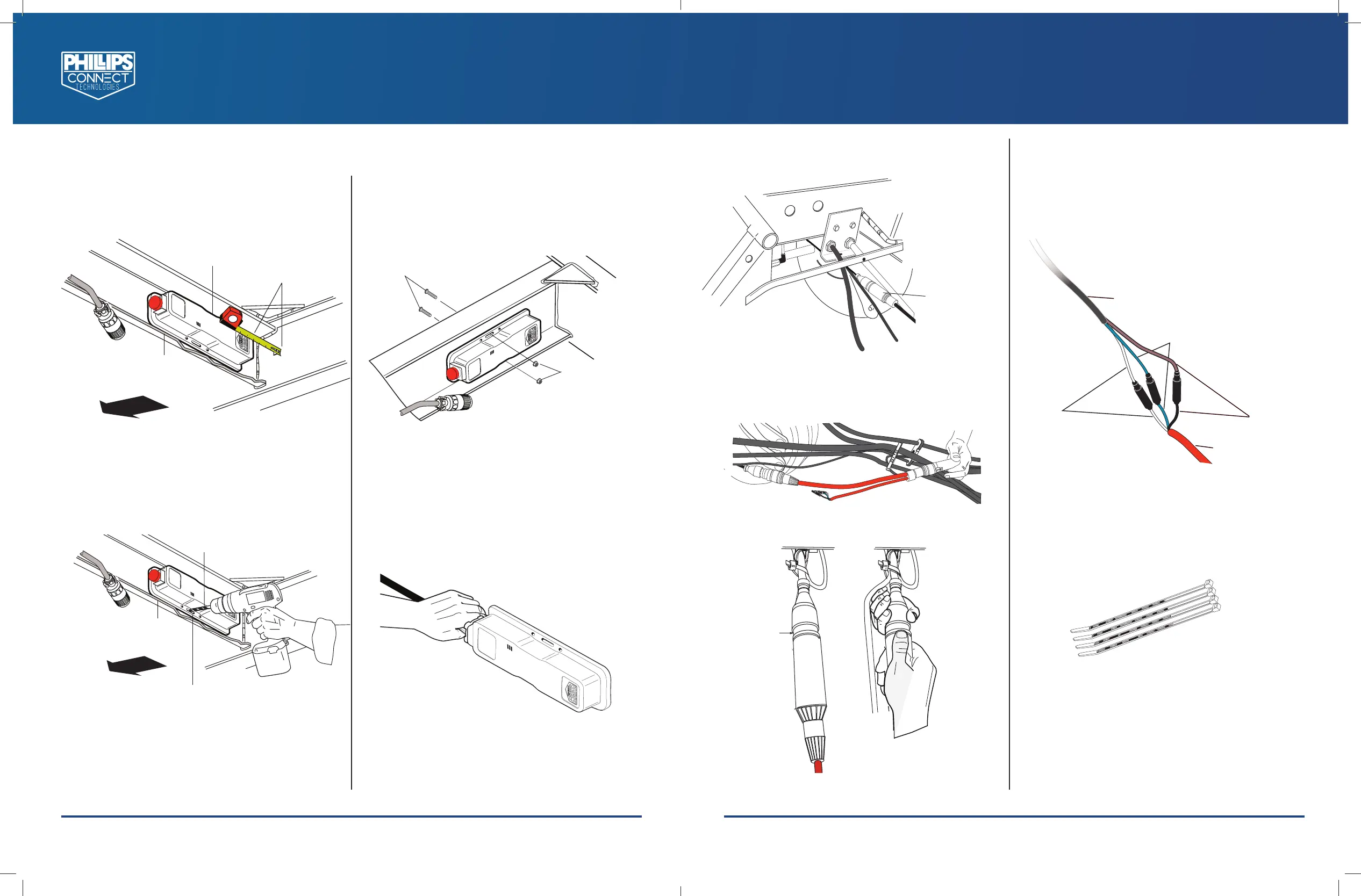
1. Mount at least 2 inches from the frame
rail so the EZTrac™ Plus Gateway has a clear
view to the ground.
Use a 3/16” Drill Bit
Channel Cut
Away for Clarity
Use EZTrac™ Plus Gateway as a Tem-
plate, Making Sure the Gateway is
at least 2” from the Curb Side Frame
Rail
2. Using the EZTrac™ Plus Gateway as a
template, mark and drill two (2) 3/16"
holes as shown.
(2) Buttonhead Torx Screws
Stainless Steel, 8-32 Thread
Size, 1 1/4” Long
(2) 18-8 Stainless
Steel Serrated
Flange Locknut
8-32 Thread Size
3. Insert supplied 8-32 button head screws from
the front side and secure with 8-32 serrated
flange nuts.
4. Plug in the Power Extension Harness to the
EZTrac™ Plus Gateway.
IMPORTANT: Insert the connector and turn ¼
turn clockwise until it clicks into place.
Front of
Chassis or
Trailer
Front of
Chassis or
Trailer
Page 3
PHILLIPS CONNECT TECHNOLOGIES
TRANSPORTATION TECHNOLOGIES REIMAGINED
PCT-EZTPIG REV0_8-21-19
Black to Black
ABS Extention Harness
Power Extention Harness
White to White
Blue To Blue
connect Here
ABS Harness Connector
Plug in he ABS Extension Harness in the Middle as Shown
PHILLIPS CONNECT TECHNOLOGIES
12012 BURKE STREET, SANTA FE SPRINGS, CA 90670
TEL: 888.880.6890
WWW.PHILLIPS-CONNECT.COM
5. Locate the ABS TTMA 5 pin connector and
unplug it from the main harness.
Locate The TTMA
5 pin ABS Connector
Locate the ABS
TTMA 5 Pin
Connector
6. Plug in the ABS Extension Harness.
Connect Here
ABS Extension Harness
Connector
Plug in the ABS Extension Harness in the
Middle as Shown
Plug in the Power Extension Harness to
the ABS Extension Harness.
Power Extension Harness
Blue to Blue
Brown to
Brown
ABS Extension
Harness
White to
White
7. Matching the colored wires as shown below,
plug the three (3) male .180 bullet connectors
on the Power Extension Harness (currently
connected to the Gateway) into the three (3)
female .180 bullet connectors on the ABS
Extension Harness (currently installed on
the main harness).
8. Secure all loose harnesses with the included
cable ties. Use side cutter to cut back excess
cable ties.
9. Power up the asset.
 Loading...