2.2 Setting up your MPS as PV Charge Controller (stand-alone mode)
Please be sure to always follow this procedure in the following sequence:
Set the DIP switches according to the PV charge controller function
Mount MPS on DIN Rail or wall
Connect the battery to the unit with proper polarity
Connect the solar array to the unit
When disassembling, perform the installation sequence in reverse order.
Note: Changes to DIP switches after connecting the unit to the battery do not affect the function
of the unit.
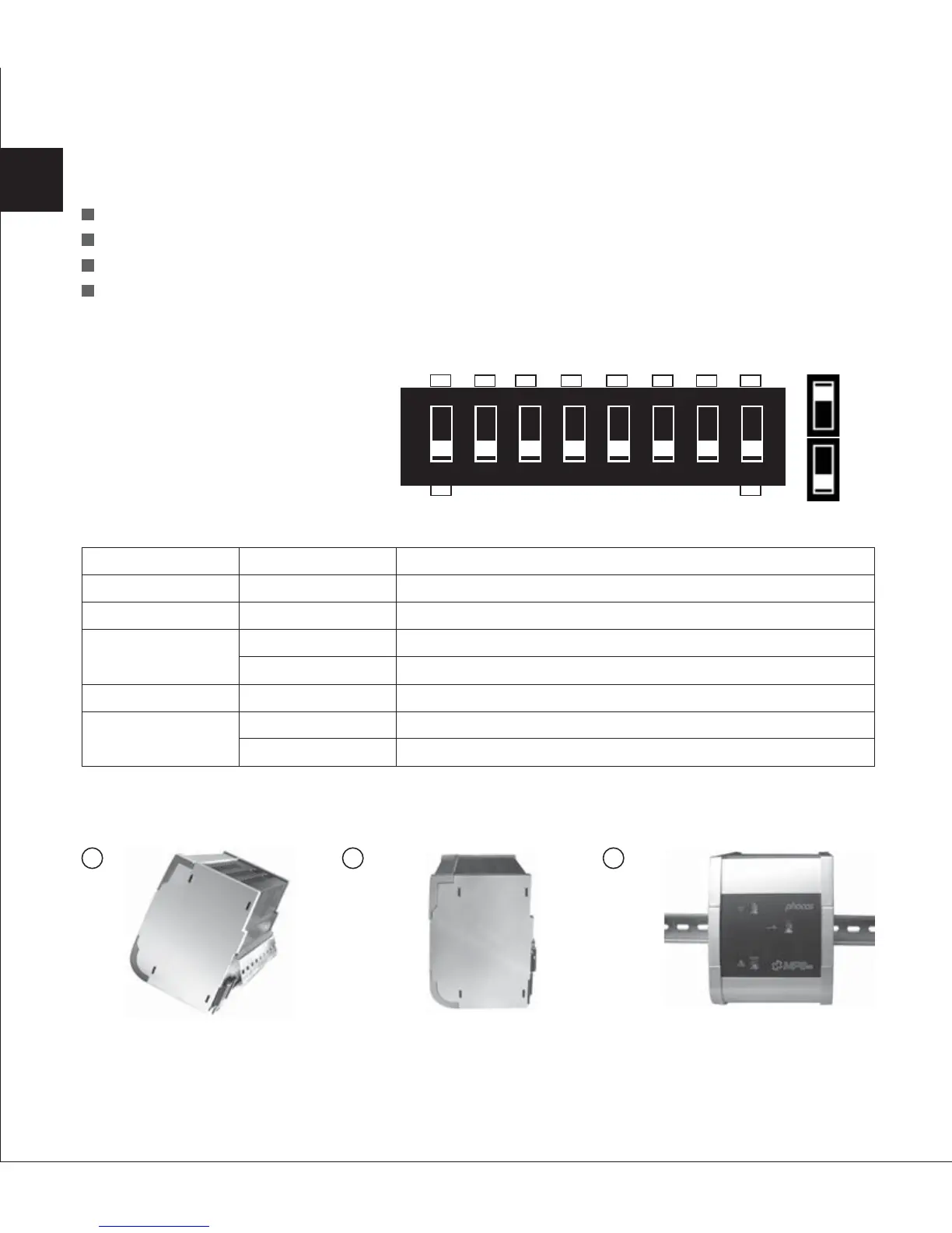
2.2.1 Setup DIP Switches
The MPS comes with an eight pole
DIP-switch, which can be used to
set up your MPS.
Setting
ON
ON
ON
OFF
OFF
ON
OFF
Function
Activates MPS as charge controller
Activates MPS as PV charge controller
Activates PWM
Activates two-point control
Stand-alone function
Gel/AGM battery
Liquid lead acid battery
DIP NO.
DIP 8
DIP 7
DIP 6
DIP 5
DIP 4
2.3 Installation Instruction
2.3.1 Wall Mounting
Please see fig 1, 2 and 3 showing how to install the MPS controller on a standard 35 mm DIN Rail.
Mount DIN Rail onto a vertical surface.
Adjust the DIP switch settings according to your requirements: (DIP1,DIP2 and DIP3 are unused)
34
1 2
3
EN
+
-
12345678
SAB
ON
OFF
 Loading...