2.4 Starting up the Controller
After double-checking all wires and terminals, insert battery fuse.
2.4.1 Self Test
As soon as battery voltage is applied to MPS, the unit begins a self test routine and wiring-
check. If system passes wiring-check, the LED display changes to "normal operation."
2.4.2 Display Functions
Status indication
Meaning
Battery charging
In PWM mode:
solar-array voltage < battery voltage
On two-point control:
solar-array voltage < battery voltage
In PWM mode: current limited by PWM
Over-current or over-temperature
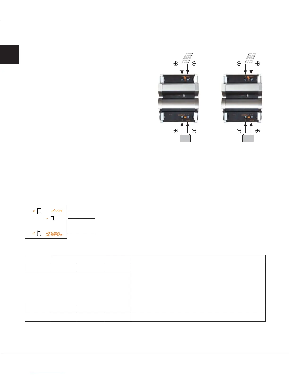
Negative grounded Positive grounded2.3.4 Connecting Solar-Array
Open the cover at the solar-array terminals.
Connect the wires leading to the solar-array
with the correct polarity. Respect the different
wiring for negative and positive grounded
systems!
Wire size: See "Table of recommended wiring
for MPS units" on page 3.
Close the covers.
36
LED 1
ON
ON
ON
OFF
LED 2
ON
OFF
FLASH
OFF
LED 3
OFF
OFF
OFF
ON
Status
OK
Error
LED 3 (Red)
LED 1 (Yellow)
LED 2 (Green)
EN
 Loading...