AXC 1050 (XC)
32
PHOENIX CONTACT 8482_de_03
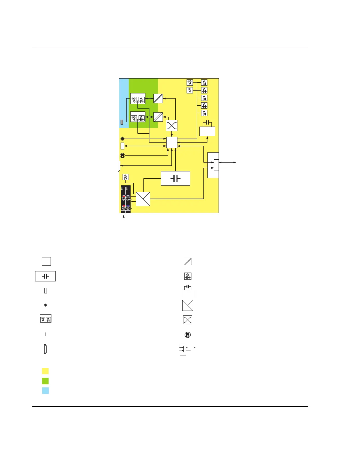
3.9 Internal basic circuit diagram
Figure 3-10 Internal basic circuit diagram (AXC 1050 (XC))
Key:
RJ45
LNK ACT
RJ45
RTC
24 V
3.3 V
U
Bus
UL
U
24 V
L
U
L
USB
Reset
FE
FAIL
RUN
BF
SF
DBG
D
E
U
Bus
Local bus
FE
Ethernet
LNK ACT
μC
Microprocessor Transmitter
UPS LED
Service interface (Micro-USB type B) Real-time clock
Reset button Power supply unit
RJ45 interface Ethernet switch
Functional earth ground connection Mode selector switch
SD card holder Axioline F local bus
The colored areas in the basic circuit diagram represent electrically isolated areas:
Logic
Ethernet interface
Functional earth ground
μC
RTC
24 V
3.3 V
U
Bus
RJ45
LNK ACT
U
Bus
Local bus
 Loading...


