AXC 1050 (XC)
34
PHOENIX CONTACT 8482_de_03
3.10.1 Ethernet
Two Ethernet interfaces (X1/X2) are available on the controller for connecting the Ethernet
network.
The Ethernet network is connected via RJ45 sockets.
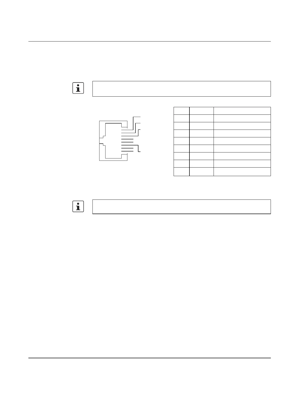
The contact assignment of the interface is as follows:
Figure 3-12 Ethernet interface and pin assignment
• Use an Ethernet cable which corresponds to CAT5 of IEEE 802.3 at least.
• Observe the bending radii of the Ethernet cables used.
Pin Signal Meaning
1 T+ Transmit data +
2 T- Transmit data -
3 R+ Receive data +
4– –
5– –
6 R- Receive data -
7– –
8– –
The Ethernet interfaces are able to switch over the transmitter and receiver automatically
(auto crossover).
RJ45
Pin 1
Pin 2
Pin 3
Pin 4
Pin 5
Pin 6
Pin 7
Pin 8
 Loading...


