Mounting hardware
8482_en_03 PHOENIX CONTACT 37
4 Mounting hardware
4.1 Safety notes
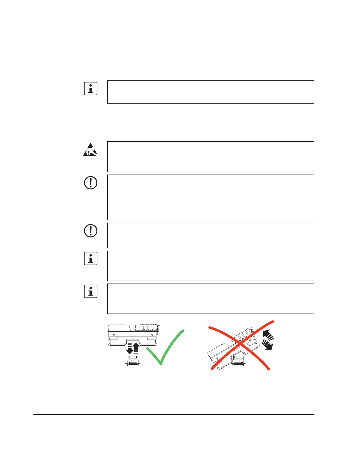
Figure 4-1 Placing the module vertically
For basic information about the Axioline F system and its installation, particularly mount-
ing/removing Axioline F modules, please refer to the UM EN AXL F SYS INST user man-
ual ("Axioline F: system and installation").
NOTE: Electrostatic discharge!
The device contains components that can be damaged or destroyed by electrostatic dis-
charge. When handling the device, observe the necessary safety precautions against
electrostatic discharge (ESD) according to EN 61340-5-1 and IEC 61340-5-1.
NOTE: Electrical damage due to inadequate external protection – no safe fuse trip
in the event of an error
The electronics in the device are damaged due to inadequate external protection.
• Protect the supply voltage externally in accordance with the connected load (number
of Axioline F devices/amount of logic current consumption for each device).
• Make sure the external fuse blows safely in the event of an error.
NOTE: Damage to the contacts when tilting
If the controller/modules tilt, you can damage the contacts.
• Place the modules onto the DIN rail vertically (see Figure 4-1).
Please note:
• During all work on the Axioline F station, the controller or a module, switch off the
power supply to the Axioline F station and make sure the supply voltage is protected
against unauthorized re-activation.
The controller is automatically grounded (FE) when it is snapped onto a grounded
DIN rail.
On the back of the controller there are two FE springs that make contact with the DIN rail
when the controller is placed on the DIN rail.
 Loading...


