Mounting hardware
8482_en_03 PHOENIX CONTACT 39
End brackets Mount end brackets on both sides of the Axioline F station. They ensure that the Axioline F
station is correctly mounted. End brackets secure the station on both sides and keep it from
moving from side to side on the DIN rail. Phoenix Contact recommends using the following
end brackets:
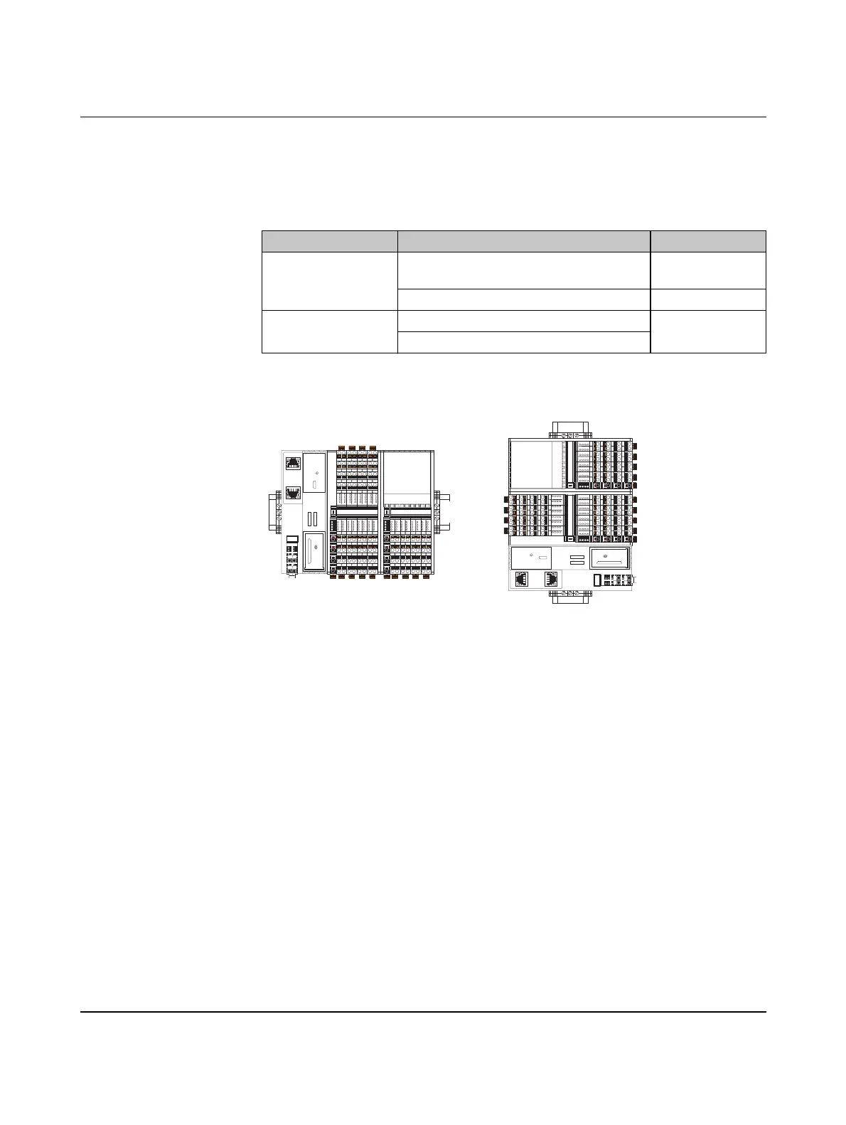
Mounting position As standard, mount the controller in a horizontal position on the DIN rail provided for that
purpose (A in Figure 4-2).
Figure 4-2 Horizontal (A) and vertical (B) mounting position
Other mounting positions are possible, however, derating may be required (see Section A
2, “Derating for the controller AXC 1050 XC”).
Note the ambient temperatures and any other special features (e.g., derating) specified in
the device/module-specific documentation for the Axioline F devices.
Table 4-1 Recommended end brackets
Mounting position Ambient conditions End bracket
Horizontal; A in
Figure 4-2 on page 39
Normal CLIPFIX 35,
CLIPFIX 35-5
High shock and vibration load E/AL-NS 35
Other; B in Figure 4-2
on page 39
Normal E/AL-NS 35
High shock and vibration load
D
UI
E1
E2
a2
b1
b2
a1
16
06
26
36
07
17
27
37
04
24
14
34
05
15
25
35
32
22
12
02 03
13
23
33
00
10
20
30
01
11
21
31
D
UA
E1
E2
a2
b1
b2
a1
16
06
26
36
07
17
27
37
04
24
14
34
05
15
25
3532
22
12
02 03
13
23
33
00
10
20
30
01
11
21
31
56
46
66
76
47
57
67
77
44
64
54
74
45
55
65
7572
62
52
42 43
53
63
73
40
50
60
70
41
51
61
71
D
UI
E1
E2
a2
b1
b2
a1
16
06
26
36
07
17
27
37
04
24
14
34
05
15
25
35
32
22
12
02 03
13
23
33
00
10
20
30
01
11
21
31
D
UA
E1
E2
a2
b1
b2
a1
16
06
26
36
07
17
27
37
04
24
14
34
05
15
25
35
32
22
12
02 03
13
23
33
00
10
20
30
01
11
21
31
56
46
66
76
47
57
67
77
44
64
54
74
45
55
65
75
72
62
52
42 43
53
63
73
40
50
60
70
41
51
61
71
8482B018
A B
 Loading...


