PHOENIX CONTACT GmbH & Co. KG
Flachsmarktstraße 8, 32825 Blomberg, Germany
Fax +49-(0)5235-341200, Phone +49-(0)5235-300
MNR 9067492
phoenixcontact.com
MACX MCR-VDC 2906242
MACX MCR-VDC-PT 2906243
+24V
GND
I
OUT
GND
I
U
OUT
GND
U
24 V
120 V
170 V
250 V
370 V
550 V
N
80 V
54 V
36 V
1.3 1.4 3.1 3.2 3.3 3.4
5.4 5.3 5.2 5.1 4.4 4.3 4.2 4.1
OUT
IN
0,5-0,6 Nm
5-7 lb In
7 mm
AWG 24-14
0,2-2,5 mm
2
MACX MCR-...
A
B
A
A
B
8 mm
AWG 24-16
0,2-1,5 mm
2
MACX MCR-...-PT
DE Einbauanweisung für die Elektrofachkraft
EN Installation notes for electrically skilled persons
2022-04-25
© PHOENIX CONTACT 2022
DNR 83161378 - 07
PNR 106309 - 07
DEUTSCHDEUTSCHENGLISHENGLISH
4 Status- und Diagnoseanzeigen
5 Installation
IEC61010-1:
Die Belegung der Anschlussklemmen zeigt das Blockschaltbild. ()
Rasten Sie das Gerät im Schaltschrank auf eine 35mm-Tragschiene nach
EN 50022 auf. ()
Die Einbaurichtung ist durch die Beschriftung auf dem Modul vorgegeben.
5.1 Spannungsversorgung
Die Spannungsversorgung (24VDC) des Moduls erfolgt an den Klemmen 1.3 und
1.4 (siehe Blockschaltbild). ()
6 Moduleinstellungen
Bevor Sie den gewünschten Spannungsmessbereich festlegen, müssen Sie das
Gerät mithilfe der DIP-Schalter ausgangsseitig einstellen. (, , )
Name Farbe / Zustand Beschreibung
PWR Grün ein Versorgungsspannung vorhanden
Grün blinkend Konfigurationsmodus
Aus Versorgungsspannung ist nicht vorhanden
STAT Rot ein Interner Fehler - tauschen Sie das Gerät aus
Rot blinkend Über- oder Unterschreitung der eingestellten Werte-
grenzen am Ausgang
Rot blinkend (3x) Modul auf Werkseinstellung setzen
(Konfigurationsmodus)
Rot blinkend
schnell
Bedienfehler, falsche Konfiguration
Grün ein Zero/Span-Werte verändern (Konfigurationsmodus)
Grün blinkend (3x) Konfiguration speichern (Konfigurationsmodus)
ACHTUNG: Elektrostatische Entladung
Treffen Sie Schutzmaßnahmen gegen elektrostatische Entladung, bevor
Sie das Gerät bedienen oder installieren.
VORSICHT: Verletzungsgefahr
Stellen Sie sicher, dass Sie alle Modulstecker montieren, bevor Sie das
Gerät in Betrieb nehmen.
Ziehen Sie die Modulstecker nicht unter Last vom Gerät ab, um einen Licht-
bogen zu vermeiden.
VORSICHT: Verletzungsgefahr
Um Arbeiten unter gefährlicher Spannung zu vermeiden, setzen Sie zum
Abgleichen nur Quellen ein, die nach IEC61010-1 6.3.1 nicht als
"GEFÄHRLICH AKTIV" gelten.
ACHTUNG
Bei Spannungsmessungen von <600V (Überspannungskategorie II) oder
<300V (Überspannungskategorie III) sind keine zusätzlichen Sicherheits-
abstände zu benachbarten Bauteilen erforderlich. In diesem Fall besteht
Basisisolierung.
Weitere Informationen zu Sicherheitsabständen finden Sie im zugehörigen
Datenblatt unter phoenixcontact.com.
• In der Gebäudeinstallation müssen Trennvorrichtungen und Neben-
stromkreisschutzeinrichtungen mit geeigneten AC- oder DC-Werten vor-
gesehen werden.
• Das Gerät ist für den Einbau in einen Schaltschrank oder in ein vergleich-
bares Gehäuse vorgesehen. Das Gerät darf nur eingebaut betrieben
werden. Der Schaltschrank muss den Anforderungen eines Brand-
schutzgehäuses der Sicherheitsnorm UL/IEC61010-1 entsprechen und
einen adäquaten Schutz vor elektrischem Schlag oder Verbrennungen
bieten.
• Sehen Sie in der Nähe des Gerätes einen Schalter/Leistungsschalter
vor, der als Trennvorrichtung für dieses Gerät gekennzeichnet ist.
• Sehen Sie eine Überstromschutzeinrichtung (I 16A) in der Installation
vor.
• Bauen Sie das Gerät zum Schutz gegen mechanische oder elektrische
Beschädigungen in ein entsprechendes Gehäuse mit einer geeigneten
Schutzart nach IEC60529 ein.
• Trennen Sie das Gerät bei Instandhaltungsarbeiten von allen wirksamen
Energiequellen.
• Wenn das Gerät nicht entsprechend der Dokumentation benutzt wird,
kann der vorgesehene Schutz beeinträchtigt sein.
DIP Position Beschreibung
S1.1 OFF Bleibt immer auf OFF
S1.5/S1.6 Einstellung des zu messenden Spannungsbereichs
()
S1.7 OFF Mittelwertbildung aus: Ausgangssignal wird unge-
glättet ausgegeben, sprunghafte Änderungen sind
sichtbar
ON Mittelwertbildung ein: Ausgangssignal wird geglät-
tet ausgegeben
S1.8 OFF Ausgangssignale: -10V...10V, -20mA...20mA
ON Ausgangssignale: 2V...10V, 4mA...20mA
S1.2 OFF Konfiguration abschließen, Modul wechselt in Be-
triebsmodus
ON Modul wechselt in Konfigurationsmodus
Voltage transducer (DC) for analog signals
1 Safety regulations
• The devices described in this document are for use in manufacturing industry
environments. They are not designed for use in private environments. They are
as Class A devices.
• Installation, operation, and maintenance may only be carried out by qualified
electricians. Follow the installation instructions as described.
• These devices are Class A items of equipment (EN 61000-6-4). When using
the equipment in residential areas, it may cause radio interference. In this case,
the operator is obligated to implement appropriate measures.
• The products are built according to the latest safety requirements. However,
dangerous situations or damage to the products or other property can arise
from misuse of this device.
• The device fulfills the requirements of the EMC directives and harmonized
European standards. Any modifications to the systems can influence the
EMC behavior.
• The installer of the system is responsible for the safety of the system in which
the device is installed.
• When installing and operating the device, observe the applicable regulations
and safety directives (including national safety directives), as well as the gen-
erally recognized technical regulations.
• Observe the safety information, conditions, and limits of use specified in the
product documentation. Comply with them.
• The device must not be opened or modified. Do not repair the device yourself,
replace it with an equivalent device. Repairs may only be carried out by the
manufacturer. The manufacturer is not liable for damage resulting from viola-
tion.
• The device is not designed for use in atmospheres with a danger of dust explo-
sions.
• Once new configuration data has been written, the device performs a warm
start that changes the properties of the device. Adapt the following control de-
vice to these modifications.
2 Short description
With the voltage transducer, you can record voltages in various measured value
ranges from 0VDC...±24VDC to 0VDC...±550VDC and convert the to stan-
dardized analog signals.
The output signal (e.g.0...20mA) can be adjusted to the measured values of the
voltage input with the multi-function wheel (, 3) to the maximum value (20mA):
either by using the ZERO/SPAN configuration or the Teach-in configuration.
The device is calibrated by default to 0VDC...24VDC on the input and
0mA...20mA on the output.
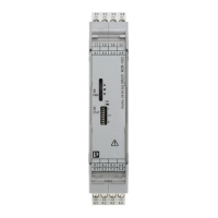
3 Operating and indicating elements ()
1 Supply voltage
2 Output: Standard signals
3 Multi-function wheel S2
4 Green “PWR” LED, power supply
5 LED red/green "STAT" status LED
6 DIP switch S1
7 Cover
8 Input: Measuring voltage
9 Snap-on foot for DIN rail mounting
You can download the latest documents at phoenixcontact.net/products.
NOTE
Ensure the specified distance between the voltage measurement input and
other conductive parts nearby is observed. This safety distance is required
to prevent electrical flashovers.
WARNING: Danger to life by electric shock!
The device is only to be used as described here. Phoenix Contact accepts
no liability if the device is used for anything other than its designated use.
Any use other than the designated use may lead to malfunction or irrevers-
ible damage of the device.
The IP20 protection (IEC 60529/EN 60529) of the device is intended for use
in a clean and dry environment. Install the module in a housing with at least
IP54 degree of protection according to EN 60529. The stated limits concern-
ing mechanical or thermal loads on the module may not be exceeded.
Cover termination area after installation in order to avoid accidental contact
with live parts (e. g., installation in control cabinet).
The device contains valuable recyclable materials, which should be utilized.
Dispose of the device separately from other waste, i.e., via an appropriate
collection site.
Warning! Read through the operating manual carefully.
4 Status and diagnostics indicators
5 Installation
IEC61010-1:
The assignment of the connection terminal blocks is shown in the block diagram.
()
Snap the device onto a 35 mm DIN rail according to EN 50022 in the control cab-
inet. ()
The installation direction is indicated by the marking on the module.
5.1 Power supply
The module is supplied with power (24VDC) via terminals 1.3 and 1.4
(see block diagram). ()
6 Module settings
Prior to specifying the voltage measurement range required, the device must be
set at the output side using the DIP switches. (, , )
Name Color/status Description
PWR Green on Supply voltage present
Flashing green Configuration mode
Off No supply voltage
STAT Red on Internal error - replace the device
Flashing red Values above or below the limits set on the output
Flashing red (3x) Reset module to factory settings (configuration mode)
Flashing red, fast Operation error, incorrect configuration
Green on Change zero/span values (configuration mode)
Flashing green (3x) Save configuration (configuration mode)
NOTE: Electrostatic discharge
Take protective measures against electrostatic discharge before operating
or installing the device.
CAUTION: Risk of injury
Be sure to attach all module plugs before starting up the device.
To prevent an electric arc, do not disconnect the module plug from the de-
vice under load.
CAUTION: Risk of injury
To avoid work under hazardous voltage, only use sources for calibration that
are not considered "HAZARDOUS ACTIVE" according to
IEC61010-1 6.3.1.
NOTE
For voltage measurements <600V (overvoltage category II) or <300V
(overvoltage category III), no additional safety distances from neighboring
components are necessary. Basic insulation exists in this case.
Further information on safety distances can be found in the associated data
sheet at phoenixcontact.com.
• Disconnecting devices and branch circuit protection with suitable AC or
DC rating shall be provided in the building installation.
• The device is intended for installation in a control cabinet or in a compa-
rable enclosure. The device may only be operated when it has been in-
stalled. The control cabinet must meet the requirements of
UL/IEC61010-1 in terms of protection against spread of fire and protec-
tion against electric shock or burn.
• Provide a switch/circuit breaker close to the device, which is labeled as
the disconnecting device for this device.
• Provide overcurrent protection (I ≤16A) within the installation.
• To protect the device against mechanical or electrical damage, install it
in a suitable housing with appropriate degree of protection as per
IEC60529.
• During maintenance work, disconnect the device from all effective power
sources.
• If the device is not used as described in the documentation, the intended
protection can be negatively affected.
DIP Position Description
S1.1 OFF Always remains in the OFF position
S1.5/S1.6 Setting the voltage range to be measured ()
S1.7 OFF Mean-value generation off: output signal is output
unsmoothed; abrupt changes are visible
ON Mean-value generation on: output signal is output
smoothed
S1.8 OFF Output signals: -10V...10V, -20mA...20mA
ON Output signals: 2V...10V, 4mA...20mA
S1.2 OFF Close configuration; module switches to operating
mode
ON Module switches to configuration mode
Spannungsmessumformer (DC) für Analogsignale
1 Sicherheitsbestimmungen
• Die in diesem Dokument beschriebenen Geräte sind für den Einsatz im Ferti-
gungsindustriebereich ausgelegt. Sie sind nicht für den Einsatz im privaten
Umfeld ausgelegt. Es handelt sich um Class A-Geräte.
• Die Installation, Bedienung und Wartung ist von elektrotechnisch qualifiziertem
Fachpersonal durchzuführen. Befolgen Sie die beschriebenen Installationsan-
weisungen.
• Diese Geräte sind Betriebsmittel der Klasse A (EN 61000-6-4). Dieses Be-
triebsmittel kann im Wohnbereich Funkstörungen verursachen. In diesem Fall
ist der Betreiber verpflichtet, angemessene Maßnahmen zu ergreifen.
• Die Produkte werden nach den neuesten Sicherheitsanforderungen gefertigt.
Eine missbräuchliche Verwendung des Geräts kann jedoch zu Gefahrensitua-
tionen sowie Produkt- oder anderen Sachschäden führen.
• Das Gerät erfüllt die Anforderungen der EMV-Richtlinie und der harmonisierten
europäischen Normen. Jedwede Modifikation der Systeme kann die elektro-
magnetische Verträglichkeit beeinflussen.
• Die Verantwortung für die Sicherheit des Systems, in das dieses Gerät einge-
baut ist, liegt beim Monteur des Systems.
• Halten Sie die für das Errichten und Betreiben geltenden Bestimmungen und
Sicherheitsvorschriften (auch nationale Sicherheitsvorschriften) sowie die all-
gemein anerkannten Regeln der Technik ein.
• Beachten Sie die Sicherheitsinformationen, Bedingungen und Einsatzgrenzen
in der Produktdokumentation. Halten Sie diese ein.
• Öffnen oder Verändern des Geräts ist nicht zulässig. Reparieren Sie das Gerät
nicht selbst, sondern ersetzen Sie es durch ein gleichwertiges Gerät. Repara-
turen dürfen nur vom Hersteller vorgenommen werden. Der Hersteller haftet
nicht für Schäden aus Zuwiderhandlung.
• Das Gerät ist nicht für den Einsatz in staubexplosionsgefährdeten Atmosphä-
ren ausgelegt.
• Nach dem Schreiben neuer Konfigurationsdaten führt das Gerät einen Warm-
start durch, durch den sich die Eigenschaften den Gerätes ändern. Passen Sie
das nachfolgende Steuergerät auf diese Änderungen an.
2 Kurzbeschreibung
Mit dem Spannungsmessumformer können Sie in verschiedenen Messwertberei-
chen Spannungen von 0VDC...±24VDC bis 0VDC...±550VDC erfassen
und in normierte Analogsignale umsetzen.
Sie können das Ausgangssignal (z.B. 0...20mA) mit dem Multifunktionsrad
(, 3) an die Messwerte vom Spannungseingang auf den Maximalwert (20mA)
anpassen: entweder mit der ZERO/SPAN-Konfiguration oder mit der Teach-In-
Konfiguration.
Das Gerät ist werksseitig auf 0VDC...24VDC am Eingang und 0mA...20mA
am Ausgang abgeglichen.
Der Ausgang ist kurzschlussfest.
3 Bedien- und Anzeigeelemente ()
1 Versorgungsspannung
2 Ausgang: Normsignale
3 Multifunktionsrad S2
4 LED grün "PWR" Spannungsversorgung
5 LED rot/grün "STAT" Status-LED
6 DIP-Schalter S1
7 Abdeckung
8 Eingang: Messspannung
9 Rastfuß für Tragschienenmontage
Aktuelle Dokumente können unter der Adresse
phoenixcontact.net/products heruntergeladen werden.
ACHTUNG
Halten Sie die Abstandsvorgaben des Spannungsmesseingangs zu ande-
ren leitenden Teilen in der Umgebung ein. Dieser Sicherheitsabstand ist er-
forderlich zur Vermeidung von elektrischen Überschlägen.
WARNUNG: Lebensgefahr durch Stromschlag!
Das Gerät ist ausschließlich für den hier beschriebenen Gebrauch be-
stimmt. Bei nicht bestimmungsgemäßer Verwendung übernimmt
Phoenix Contact keine Haftung. Jegliche vom bestimmungsgemäßen Ge-
brauch abweichende Verwendung könnte Fehlfunktionen oder irreversible
Schäden am Gerät verursachen.
Die Schutzart IP20 (IEC 60529/EN 60529) des Gerätes ist für eine saubere
und trockene Umgebung vorgesehen. Bauen Sie das Modul in ein Gehäuse
mindestens der Schutzart IP54 nach EN 60529 ein. Die beschriebenen
Grenzen für mechanische oder thermische Beanspruchungen des Moduls
dürfen nicht überschritten werden.
Nach der Installation den Klemmenbereich abdecken, um unzulässiges Be-
rühren spannungsführender Teile zu vermeiden (z. B. Einbau im Schalt-
schrank).
Das Gerät enthält wertvolle recyclingfähige Materialien, die einer Verwer-
tung zugeführt werden sollen.
Entsorgen Sie das Gerät getrennt vom Hausmüll über geeignete Sammel-
stellen.
Warnung! Lesen Sie die Bedienungsanleitung sorgfältig
durch.