Description of the RFC 4072S
108580_en_02 PHOENIX CONTACT 49 / 272
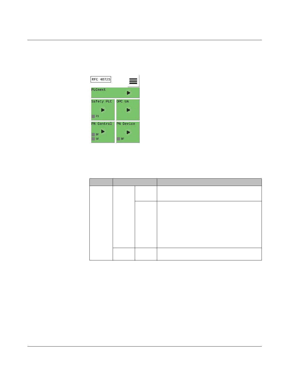
2.9.3 Diagnostics indicators
The diagnostic indicators of all the tiles are displayed in the home menu using virtual LEDs.
They have the following meaning:
Figure 2-16 Diagnostic indicators in the home menu (LEDs)
Safety PLC (safety-related
PROFINET controller
iSPNS 3000)
OPC UA (OPC UA server) No LED indicators present.
Table 2-7 Diagnostics indicators: safety PLC (safety-related PROFINET controller
iSPNS 3000)
LED Color Meaning
FS Red On A critical error has occurred and been detected.
The iSPNS 3000 has switched to the “safe state”.
Flash-
ing, 1 Hz
– Initialization phase is running (firmware boot pro-
cess with power-on self-test, loading the param-
eterization and configuration data from the
parameterization memory, booting the safe appli-
cation program) or
– Initialization phase has been aborted with an
error or
– Error-free DEBUG state of the iSPNS 3000
Gray Off Error-free operating state of the iSPNS 3000 (if supply
voltage is present)
 Loading...


