LEFT RIGHT
1 2
3 4
5 6
7 8
9 10
11 12
+
_
INT
CTRL
INTERFACE
EXPANSION PORT
0
4
1
2
3
1 2
4
5
6
7
8
9
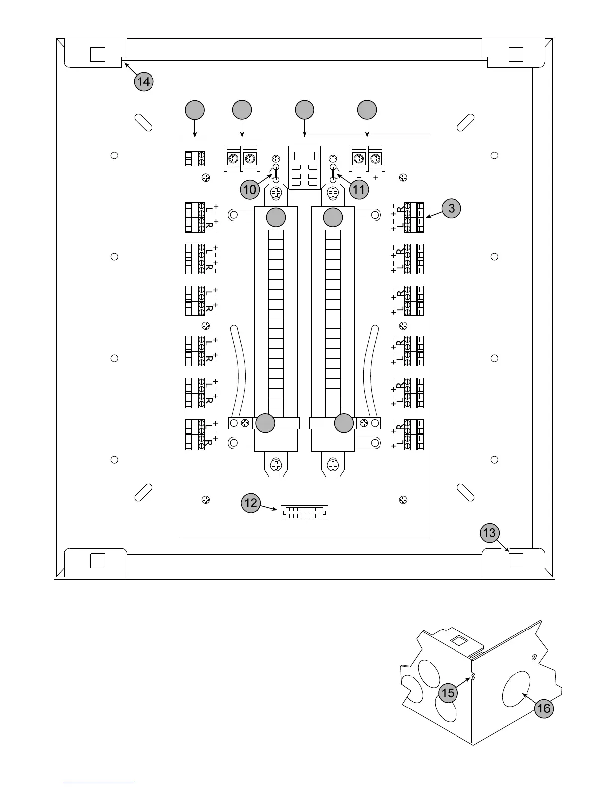
1. Left Amplifier Input
2. Right Amplifier Input
3. Numbered Speaker Output Zone
4. Left Channel Power Resistor
5. Adjustable Left Channel Resistance Adjustment Tap
6. Right Channel Power Resistor
7. Adjustable Right Channel Resistance Adjustment Tap
8. Interface Socket for Optional HDB1 Door Bell Interrupt Module
9. HDB1 Interrupt Control Terminal for Switched 12 - 16 VAC Door Bell Signal
10. Left Channel Interface Socket Bypass Jumper. Cut when using the HDB1
11. Right Channel Interface Socket Bypass Jumper. Cut when using the HDB1
12. Expansion Socket for Optional Zone Switching Modules (See Features)
13. Mounting Tab for the Cover Mounting Push-lock Receptacles
14. Speaker Wire Stripping Guide
15. 1/2” and 5/8” Drywall Alignment Markers
16. Wiring Knockout for the Supplied Snap-in Strain Reliefs