38
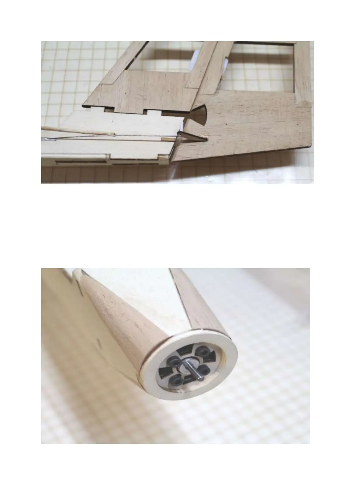
Since the tail units and control horns are only glued after the model has been covered, the photo is intended to illustrate
the linkage to the rudders for demonstration purposes. Shown without elevator.
Bend the linkage wire by 90° at the height of the hole in the control horn.
Shorten the linkage wire to a leg length of approx. 10 mm.
Push the linkage wire through the hole in the control horn
Cut off a part approx. 6 mm long from the Bowden cable cover
Push this section onto the leg of the linkage wire and secure with a small (!!) drop of superglue. This prevents the guide
wire from accidentally slipping out.
Installation of the electric drive