Do you have a question about the PINARELLO DOGMA F12 Series and is the answer not in the manual?
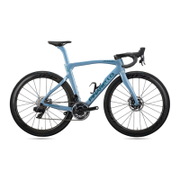
| Bottom Bracket | Italian Threaded |
|---|---|
| Pedals | Not included |
| Frame Material | Carbon Fiber |
| Fork Material | Carbon Fiber |
| Wheelset | Fulcrum |
| Handlebar | Most Talon Ultra |
| Seatpost | Pinarello Aero |
| Headset | Pinarello Integrated |
| Stem | Most Talon Ultra |
| Tires | Continental |
| Cassette | Shimano |
| Chain | Shimano |
| Crankset | Shimano Dura-Ace |
| Saddle | Fizik |
Defines the manual's intent as a guide for Dogma F12 and F12 Disk assembly for expert mechanics.
Advises users to utilize authorized Pinarello dealers for assembly, service, repairs, and maintenance.
Highlights focus on Shimano Di2 and mentions downloadable assembly videos and digital manuals.
Instructs users to inspect components for sharp edges, burrs, or cracks before assembly.
Mandates immediate contact with customer service if any cracks are found on components.
Recommends rounding edges of handlebar, stem, top cap, and spacers touching the steerer tube.
Strictly prohibits drilling, removing parts, or modifying frame components due to safety risks.
Warns against installing incompatible components, as it may compromise assembly integrity.
Details essential tightening torques and thread treatments (grease/thread-locker) for component security.
Provides minimum housing and hose lengths for rim and disc brakes, to be cut per frame/handlebar size.
Specifies recommended housing lengths for front and rear derailleur cables in mechanical groupsets.
Guides the installation of the rear brake (RB) on the frame, specifying Direct Mount compatibility.
Details the installation of the front brake (FB) on the fork, requiring Direct Mount compatibility.
Describes routing the RB housing through the frame's top tube to the head tube.
Instructs to apply a foam sleeve on the RB housing and route it into the top tube near the head tube.
Covers the installation of headset bearings and the steerer tube into the frame seat.
Details installing the upper bearing, compression ring, and headset top cap, ensuring correct notch alignment.
Routes the rear brake (RB) hose from the chainstay hole to the top tube, above the BB sleeve.
Guides the installation of the rear brake caliper to the chainstay, to be fully tightened after rotor alignment.
Routes the front brake (FB) hose through the fork and steerer tube to the exit hole.
Details installing the front brake caliper to the fork, to be fully tightened after rotor alignment.
Covers headset bearing and steerer tube installation, capturing disc brake hoses.
Details installing the compression ring and headset top cap, ensuring correct hose placement.
Specifies routing lengths and paths for RD, FD, Battery, and Di2 Interface cables to the BB sleeve.
Covers applying heat-shrink tubes, connecting junction SM-JC41, and installing the rear derailleur.
Details inserting the FD wire grommet and installing the front derailleur to the hanger.
Guides installing the Shimano Di2 battery into the seatpost and connecting the power cable.
Instructs on installing the bottom bracket, crankset, and chain, noting BB compatibility.
Details the installation of the rear derailleur onto the RD hanger.
Guides the installation of the front derailleur onto the FD hanger.
Covers installing the bottom bracket, crankset, and chain, noting BB compatibility.
Details installing the seatpost into the seat tube, including wedge and hanger tightening.
Instructs to install shift levers on the Talon Ultra handlebar following OEM specifications.
Guides routing the Y junction EW-JC130-SM from handlebar center to side exit holes.
Details connecting the Y junction to the junction port EW-JC200 and the 1000mm EW-SD50 cable.
Specifies positioning the handlebar on the steerer tube based on spacer height (X+2cm).
Routes the electronic cable connector through the headset top cap and compression ring's left notch.
Routes the 1000mm cable EW-SD50 through the headset bearing down to the DT opening.
Guides installing junction EW-RS910 into the plastic support interface and fixing it to the DT slot.
Instructs to install shift levers on the Talon Ultra handlebar following OEM specifications.
Details routing RD and FD housings through the handlebar and to the levers.
Specifies positioning the handlebar on the steerer tube based on spacer height (X+2cm).
Guides routing RD and FD housings through headset components and down to the DT opening.
Details cutting housings, installing end caps, and assembling the adjuster case and components.
Routes FD/RD wires from levers to BB, FD exit hole, seat tube, and chainstay exit hole.
Covers routing RB housing from head tube through handlebar to rear brake caliper for Di2 systems.
Details routing brake cables for rim brakes with mechanical groupsets through the integrated handlebar.
Guides routing RB and FB hoses through the Talon Ultra handlebar for disc brakes and Di2.
Details routing brake cables for disc brakes with mechanical groupsets through the integrated handlebar.
Explains adjusting handlebar stack using split spacers (10mm/5mm) and proper cable positioning.
Lists maximum allowed spacer heights based on the type of top cap used.
Details marking the steerer tube for cutting, considering options for leaving it longer.
Provides instructions on disassembling parts and the precise cutting line for the steerer tube.
Guides sliding the handlebar down, tightening the headset, and notes on split vs. standard aero spacers.
States that assembly with MOST TIGER stems and traditional bars requires a Top Cap Adapter.
Explains positioning the stem and bar considering the adapter, and the X+2cm dimension.
Details how the 20mm adapter modifies maximum allowed spacer heights with different top caps.
Provides a table for correct cable and housing routing through the adapter and around the steering tube.
Instructs to tighten the headset and ensure spacers are installed between the top cap and adapter.
Ensures final tightening and correct centering of disc and rim brakes, and proper bleeding.
Instructs to fine-tune the rear and front derailleurs according to OEM specifications.
Recommends a thorough check of all components' assembly and operation before the first ride.