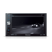
Do you have a question about the Pioneer AVH-P4000DVD and is the answer not in the manual?
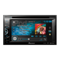
| Display Size | 6.1 inches |
|---|---|
| Resolution | 800 x 480 pixels |
| Touchscreen | Yes |
| DVD Playback | Yes |
| CD Playback | Yes |
| USB Port/Input | Yes |
| Audio Formats Supported | MP3, WMA, AAC |
| iPod Compatibility/Control | Yes |
| Aux Input | Yes |
| Preamp Outputs | 3 pairs (front, rear, subwoofer) |
| Peak Power Output | 50 watts x 4 Channels |
| Remote Control | Yes |
| Video Output | Yes |
| AM/FM Tuner | Yes |
| Equalizer | 13-band graphic equalizer |
| Bluetooth | No (Bluetooth adapter CD-BTB200 is optional) |
| Video Formats Supported | DivX, MPEG-1, MPEG-2 |
| RMS Power Output | 14 watts x 4 channels |
General safety advice for users and technicians handling the unit, including cautions and warnings.
Details on laser diode characteristics and handling precautions to avoid eye exposure.
Information on mercury in LCD backlighting and lead in electrical parts, per California regulations.
Ensures product safety and compliance with regulations during servicing operations.
Procedures for ensuring original product performance through proper adjustments and confirmations.
Guidelines for using appropriate lubricants, adhesives, and replacement parts for repairs.
Proper cleaning methods for internal components to restore performance.
Steps to protect the product from transit damage by setting shipping mode or screws.
Essential precautions for safe and effective servicing, including handling ICs, power, connectors, and touch panels.
Specific instructions and recommendations for using lead-free solder and soldering irons.
Cautions for handling sensitive components like fuses, laser diodes, and hot areas during repair.
Technical details regarding the unit's general features, power, and system capabilities.
Information on various disc formats and content types supported by the device.
Overview of the unit's front panel buttons, controls, and their functions.
Visual representation of all external connections, wiring harnesses, and interfaces.
Key checks to ensure product quality and customer satisfaction after servicing.
Visual guide to the placement of main PCBs and major modules within the unit.
List of specific jigs and tools required for various servicing operations.
Instructions for cleaning critical components like optical pickup lenses and fans before shipping.
A high-level diagram illustrating the main functional blocks and their interconnections.
Flowchart to guide the diagnostic process for operational failures and power-on sequences.
Detailed procedure for inspecting and testing the pickup unit's functionality and performance.
Systematically guides troubleshooting with flowcharts and specific component checks.
Comprehensive list of error codes with their meanings and potential reset methods.
Detailed description of connector pin functions and their associated signals.
Procedures and precautions for performing adjustments specific to the DVD playback mechanism.
Step-by-step guide for performing SKEW adjustment on the pickup unit and related components.
Adjustment points and procedures for the monitor PCB to ensure proper display functionality.
Adjustment points and procedures for the main mother PCB to ensure optimal performance.
Adjustment procedures for the invertor PCB, likely related to backlight or power functions.
Detailed instructions for calibrating the touch panel, including various modes and specifications.
Guide to the monitor adjustment menus, covering flicker, line, dimmer, color, and screen settings.
An illustrated list of all parts included in the product's packaging.
Exploded views and parts lists for the exterior components of the unit.
Detailed exploded views and parts list for the DVD mechanism module.
Circuit diagram for the analog section of the mother PCB, covering various signal paths.
Circuit diagram detailing the power supply circuitry and voltage regulation within the mother PCB.
Circuit diagram for the system control and bus interfaces of the mother PCB.
Circuit diagram illustrating the FM/AM tuner unit and its connections on the mother PCB.
Circuit diagram for the interface PCB, detailing connections for IP-BUS, digital output, and camera input.
Circuit diagram for the keyboard unit, showing button functions and connections to the main unit.
Circuit diagrams for the DVD core unit, covering signal paths and component connections.
Circuit diagrams for the compound units, likely related to sensor or mechanism control.
Circuit diagrams for the monitor PCB, including OSD and uCOM sections.
Diagram illustrating the physical layout and connectivity of connectors on the mother PCB.
Diagram showing the connector layout and pin assignments for the interface PCB.
Diagram illustrating the connector layout and button connections for the keyboard unit.
Diagram detailing the connector layout and pin assignments for the DVD core unit.
Diagrams showing the connector layout for the compound units (A and B).
Diagram illustrating the connector layout and pin assignments on the monitor PCB.
Diagram showing the connector layout for the invertor PCB, likely for LCD display connections.
List of all chip resistors used in the unit, including their circuit symbols and part numbers.
List of all chip capacitors used in the unit, including their circuit symbols and part numbers.
List of all integrated circuits (ICs) used, with their part numbers and locations.
List of all transistors used, including their part numbers and circuit symbols.
List of all diodes used, including their part numbers and circuit symbols.
List of other electronic components like inductors, coils, crystals, and fuses.



 Loading...