Do you have a question about the Pioneer DEH-2850MP/XN/ES and is the answer not in the manual?
| Power Output | 50W x 4 |
|---|---|
| RMS Power Output | 22W x 4 |
| Tuner | AM/FM |
| CD Playback | Yes |
| MP3 Playback | Yes |
| WMA Playback | Yes |
| WAV Playback | No |
| AAC Playback | No |
| USB Port | Yes |
| USB Direct Control for iPod/iPhone | Yes |
| Aux Input | Yes |
| Preamp Voltage | 2V |
| Preset EQ | Yes |
| Display Type | LCD |
| Bluetooth | No |
| Detachable Faceplate | Yes |
| Remote Control | Yes |
| Subwoofer Output | Yes |
| Preset Stations | 24 |
Safety instructions for servicing the CD mechanism, emphasizing power off and ESD protection.
Ensure safety regulations and environment are maintained during repairs.
Perform adjustments according to manual procedures for optimal performance.
Use specified lubricants and adhesives, apply proper amounts.
Clean parts like optical pickups and lenses properly to restore performance.
Set shipping mode or install screws to protect products during transit.
Covers general specifications like power source, dimensions, and weight for DEH-2800MP/XN/UC.
Details audio output power, impedance, and frequency response for DEH-2800MP/XN/UC.
Lists specifications for the CD player system, signal format, and frequency characteristics.
Provides specifications for the FM tuner, including frequency range and sensitivity.
Lists specifications for the AM tuner, including frequency range and sensitivity.
Exploded view and parts list for the packing of DEH-2800MP/XN/UC.
Exploded view and parts list for the packing of DEH-2850MP/XN/ES.
Exploded view detailing the exterior parts and their locations.
Exploded view of the CD mechanism module and its components.
High-level overview of the system's functional blocks and connections.
Illustrates the overall system connections between major modules.
Schematic diagram for the keyboard unit, showing button connections.
Schematic diagram detailing the CD mechanism module's circuitry.
PCB layout showing component placement and connector locations for the tuner amp.
PCB layout for the keyboard unit, illustrating component and connector placement.
PCB layout for the CD core unit, showing component placement.
Procedures and cautions for adjusting the CD mechanism module.
Procedure to check grating angle after replacing the pickup unit.
Details on the PCL output test program for system microcomputer diagnostics.
Step-by-step instructions for disassembling the unit, including component removal.
Pin assignments and functions for external connectors.
List of integrated circuits with pin functions and part numbers.
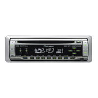
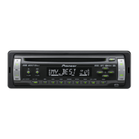
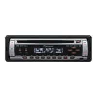
Explanation of the functions of the head unit's buttons and controls.