Do you have a question about the Pioneer DEH-P4050UB/XS/ES and is the answer not in the manual?
| Power Output | 50 W x 4 |
|---|---|
| RMS Power Output | 22 W x 4 |
| CD Playback | Yes |
| USB Port | Yes |
| USB Direct Control for iPod/iPhone | Yes |
| Aux Input | Yes |
| Bluetooth | No |
| Display Type | LCD |
| Equalizer | Yes |
| Preamp Voltage | 2V |
| Detachable Face | Yes |
| Remote Control | Yes |
| Tuner | AM/FM |
| Preset EQ | Yes |
| Playback formats | MP3, WMA |
| Dimensions | 178 x 50 mm |
| Display | White LCD (1 line with 8 characters) |
Guidelines for qualified technicians to ensure safe and proper repairs.
Information on hazardous substances present in the product.
Warnings regarding battery replacement and disposal.
Adherence to regulations and safe servicing environment.
Procedures for optimizing product performance and confirming specifications.
Guidance on using specified substances and correct application amounts.
Methods for cleaning optical parts to restore performance.
Procedures for protecting products during transit.
General safety procedures and handling instructions for technicians.
Guidelines for using lead-free solder and appropriate soldering techniques.
Detailed technical specifications for the unit.
Supported disc types and digital content formats.
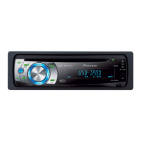
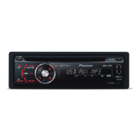
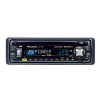
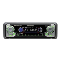
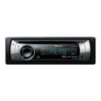
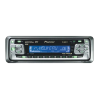
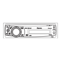
Overview of the unit's front panel controls and displays.
Specifications specific to the ES model variant.
Specifications for the IR remote control system.
Wiring diagram illustrating external connections.
Procedures to confirm product quality after repair.
Identification of main printed circuit board locations.
List of specialized tools required for service.
Recommended cleaning procedures for optical and mechanical parts.
Overall system architecture diagram.
Step-by-step flowchart for diagnosing unit operation.
Table of error codes, their displayed messages, and potential causes.
Common error messages, causes, and actions for iPod connectivity.
Common error messages, causes, and actions for USB device connectivity.
Procedure for entering and using the CD test mode for adjustments.
Method, symptoms, and purpose for checking grating angle post-PU replacement.
Step-by-step instructions for verifying the grating angle.
Steps to remove the keyboard unit assembly.
Procedure to detach the holder component.
Steps to remove the main case and front panel.
Procedure to detach the panel assembly.
Steps to remove the CD mechanism module.
Procedure to detach the tuner amplifier unit.
Instructions on how to properly hold the mechanism unit.
Steps to remove the upper and lower frames of the mechanism.
Procedure for detaching the CD core unit.
Steps to remove the pickup unit assembly.
Procedure to confirm PCL output signal frequency and range.
Exploded view and parts list for product packing.
Exploded view and parts list for external components (Part 1).
Exploded view and parts list for external components (Part 2).
Exploded view and parts list for the CD mechanism module.
High-level schematic showing system connections.
Schematic diagram for the keyboard unit.
Schematic diagram for the CD mechanism module.
Visual representations of key signal waveforms for analysis.
PCB layout and connector diagram for the tuner amp unit.
PCB layout and connector diagram for the keyboard unit.
PCB layout and connector diagram for the CD core unit.
List of miscellaneous electrical components and their part numbers.