EasyManua.ls Logo

Pioneer DEH-P544R User Manual

Pioneer DEH-P544R
98 pages
To Next Page IconTo Next Page
Page #1 background imageLoading...
Page #1 background image
MULTI-CD CONTROL HIGH POWER CD PLAYER WITH RDS TUNER
DEH-P645R EW
Se
r
v
i
c
e
M
a
nu
a
l
DEH-P545R EW
DEH-P544R EW
DEH-P443R EW
DEH-P645R
PIONEER ELECTRONIC CORPORATION 4-1, Meguro 1-Chome, Meguro-ku, Tokyo 153-8654, Japan
PIONEER ELECTRONICS SERVICE INC. P.O.Box 1760, Long Beach, CA 90801-1760 U.S.A.
PIONEER ELECTRONIC [EUROPE] N.V. Haven 1087 Keetberglaan 1, 9120 Melsele, Belgium
PIONEER ELECTRONICS ASIACENTRE PTE.LTD. 501 Orchard Road, #10-00, Lane Wheelock Place, Singapore 23880
C PIONEER ELECTRONIC CORPORATION 1998
ORDER NO.
CRT2148
CONTENTS
1. SAFETY INFORMATION ............................................2
2. EXPLODED VIEWS AND PARTS LIST.......................3
3. SCHEMATIC DIAGRAM ...........................................14
4. PCB CONNECTION DIAGRAM ................................40
5. ELECTRICAL PARTS LIST ........................................50
6. ADJUSTMENT..........................................................67
7. GENERAL INFORMATION .......................................73
7.1 PARTS .................................................................73
7.1.1 IC................................................................73
7.1.2 DISPLAY....................................................79
7.2 DIAGNOSIS ........................................................80
7.2.1 DISASSEMBLY .........................................80
7.2.2 TEST MODE..............................................81
7.3 BLOCK DIAGRAM ..............................................84
8. OPERATIONS AND SPECIFICATIONS.....................86
- See the separate manual CX-597(CRT1829) for the CD mechanism description, disassembly and circuit
description.
- The CD mechanism employed in this model is one of S7 series.
K-FEA. FEB. 1998 Printed in Japan
Question and Answer IconNeed help?

Do you have a question about the Pioneer DEH-P544R and is the answer not in the manual?

Pioneer DEH-P544R Specifications

General IconGeneral
Number of Channels4
TunerYes
Presets24
CD PlaybackYes
CD PlayerYes
MP3 PlaybackNo
WMA PlaybackNo
USB PortNo
Preamp Outputs3 (Front, Rear, Subwoofer)
BluetoothNo
Remote ControlYes
Detachable FaceplateYes
High-Pass FilterYes
Low-Pass FilterYes
Subwoofer OutputYes
Power Output50 Watts x 4 Channels
RMS Power Output22W x 4
Maximum output power50 Watts x 4 Channels
Tuner BandsAM, FM
EqualizerYes

Summary

SAFETY INFORMATION

Safety Precautions for those who Service this Unit

Precautions for service technicians regarding laser diode and test procedures.

EXPLODED VIEWS AND PARTS LIST

2.1 PACKING

Exploded view and parts list for packing components.

(2) CONTRAST TABLE

Comparison table for parts across different models.

2.2 EXTERIOR

Exploded view of exterior parts and their list.

2.3 CD MECHANISM MODULE

Exploded view of the CD mechanism module and its parts.

SCHEMATIC DIAGRAM

3.1 OVERALL CONNECTION DIAGRAM(GUIDE PAGE)

Overall connection diagram showing major unit interconnections.

3.2 OVERALL CONNECTION DIAGRAM(GUIDE PAGE)

Overall connection diagram for DEH-P443R/EW unit.

3.3 CD MECHANISM MODULE(GUIDE PAGE)

Schematic diagram for the CD mechanism module.

3.4 FM/AM TUNER UNIT

Schematic diagram for the FM/AM tuner unit.

3.5 KEYBOARD PCB

Schematic diagram for the keyboard PCB.

Waveforms

PCB CONNECTION DIAGRAM

4.1 TUNER AMP UNIT

PCB connection diagram for the tuner amplifier unit.

4.2 FM/AM TUNER UNIT

PCB connection diagram for the FM/AM tuner unit.

4.3 CD MECHANISM MODULE

PCB connection diagram for the CD mechanism module.

4.4 KEYBOARD PCB,SWITCH PCB

PCB connection diagram for keyboard and switch PCBs.

ELECTRICAL PARTS LIST

MISCELLANEOUS

List of miscellaneous electrical components.

RESISTORS

List of resistors used in the unit.

CAPACITORS

List of capacitors used in the unit.

ADJUSTMENT

6.1 TUNER ADJUSTMENT

Procedures for adjusting the tuner performance.

FM ADJUSTMENT

Specific adjustment steps for FM reception.

RDS SL ADJUSTMENT

Adjustment procedure for RDS SL function.

6.2 CD SECTION

Precautions and procedures for CD player section adjustments.

Flow Chart

Flow chart for CD player test mode operations.

6.3 CHECKING THE GRATING AFTER CHANGING THE PICKUP UNIT

Procedure to check grating angle after PU unit replacement.

GENERAL INFORMATION

7.1 PARTS

List of electronic components used in the unit.

7.1.1 IC

Pin functions and operations for integrated circuits.

7.1.2 DISPLAY

Diagrams showing LCD segment and common connections.

7.2 DIAGNOSIS

Procedures for diagnosing unit malfunctions.

7.2.1 DISASSEMBLY

Step-by-step guide for disassembling the unit.

7.2.2 TEST MODE

Information on entering and using the test mode for diagnosis.

New Test Mode

Details on the new test mode and key functions.

7.3 BLOCK DIAGRAM

Block diagram illustrating the overall system architecture.

OPERATIONS AND SPECIFICATIONS

8.1 OPERATIONS

Instructions for using the unit's various functions.

RFP Alert Installation

Guide for installing the RFP Alert system.

Remote Controller and Care

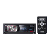
Instructions for using and caring for the remote controller.

Basic Operation

General operating procedures for tuner, CD player, and multi-CD player.

Tuner Operation

Detailed operation of tuner functions like LOCAL and BSM.

Using RDS Functions

Explanation of RDS features like AF, PI Seek, TA, and PTY.

Using the Built-in CD Player

Procedures for CD playback modes like Repeat, Scan, and Pause.

8.2 SPECIFICATIONS

Technical specifications for the unit's various systems.

Related product manuals