EasyManua.ls Logo

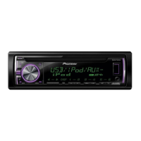
Pioneer DEH-X36UI/XNUC User Manual

Pioneer DEH-X36UI/XNUC
65 pages
To Next Page IconTo Next Page
Page #1 background imageLoading...
Page #1 background image
ORDER NO.
PIONEER CORPORATION 1-1, Shin-ogura, Saiwai-ku, Kawasaki-shi, Kanagawa 212-0031, Japan
PIONEER ELECTRONICS (USA) INC. P.O. Box 1760, Long Beach, CA 90801-1760, U.S.A.
PIONEER EUROPE NV Haven 1087, Keetberglaan 1, 9120 Melsele, Belgium
PIONEER ELECTRONICS ASIACENTRE PTE. LTD. 253 Alexandra Road, #04-01, Singapore 159936
PIONEER CORPORATION 2013
DEH-X36UI/XNUC
CRT5370
CD RDS RECEIVER
DEH-X36UI
/XNUC
DEH-X3600UI/XNUC
DEH-X3650UI/XNCS
DEH-X3650UI/XNGS
DEH-X3650UI/XNGS1
DEH-X3690UI/XNID
This service manual should be used together with the following manual(s):
Model No. Order No. Mech. Module Remarks
CX-3287
CRT4759 S11.6STD CD Mech. Module : Circuit Descriptions, Mech. Descriptions, Disassembly
K-ZZZ JULY 2013 Printed in Japan
Question and Answer IconNeed help?

Do you have a question about the Pioneer DEH-X36UI/XNUC and is the answer not in the manual?

Pioneer DEH-X36UI/XNUC Specifications

General IconGeneral
BrandPioneer
ModelDEH-X36UI/XNUC
CategoryCar Receiver
LanguageEnglish

Summary

Service Precautions

Service Precautions

General guidelines for safe and compliant servicing procedures.

Notes on Soldering

Specific instructions for using lead-free solder and soldering iron settings.

Specifications

Diagnosis

Operational Flowchart

Step-by-step guide for diagnosing power-on operations and system status.

Error Code List

A comprehensive list of error codes displayed by the unit and their detailed causes.

Service Mode

Display Test Mode 1

Mode for testing LCD display patterns and grille illumination conditions.

Display Test Mode 2

Mode for checking system microcomputer version and key illumination.

Software Version Up Method

Procedure for upgrading the system's MCU software using USB memory.

CD Test Mode

Mode for performing various CD mechanism tests and adjustments.

Disassembly

Setting and Adjustment

Schematic Diagram

Tuner Amp Unit (Guide Page)

Schematic diagram for the Tuner Amp Unit, showing component layout and connections.

PCB Connection Diagram