Do you have a question about the Pioneer KEH-P6020R and is the answer not in the manual?
| Brand | Pioneer |
|---|---|
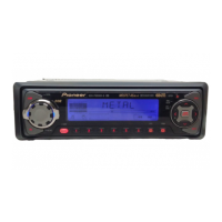
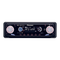
| Model | KEH-P6020R |
| Category | Car Stereo System |
| Language | English |
Lists packaging materials and components for product delivery.
Identifies external parts with their respective part numbers.
Detailed list of exterior components and their associated part numbers.
Exploded view and parts list for the cassette mechanism assembly.
Specific parts list for the cassette mechanism module components.
High-level functional overview of the unit's internal circuitry.
Visual guide showing interconnections between major circuit blocks.
PCB layout and connection points for the tuner amplifier module.
PCB layout and connection points for the front panel unit.
PCB layout and connection points for the keyboard unit.
PCB layout and connection points for the cassette mechanism module.
PCB layout and connections for the reel sense sensing circuit.
List of electrical components for the Deck Unit.
Component list for the Tuner Amp Unit for specific models.
Component list for the Keyboard Unit for KEH-P6020RB model.
Component list for the Keyboard Unit for KEH-P6020R model.
Information related to diagnosing unit issues.
Step-by-step instructions for disassembling the unit.
Explains the function of each connector pin on the unit.
Lists specific IC components used in the unit.
Detailed information and pinout for the PAL007A IC.
Details the segments and common connections for the LCD display.
Illustrates the unit's power-on sequence and microcontroller communication.
Instructions on cleaning specific parts using recommended tools.
Explains basic controls and functions of the head unit.
Details the operation of the optional steering remote control.
Explains how to use the CD-R600 remote with PGM button.
Procedure for powering the unit on and selecting sources.
How to choose between different audio sources like Tuner, Cassette, etc.
Method for powering down the unit by holding the SOURCE button.
Basic steps for operating the radio tuner, including band selection and tuning.
Instructions for inserting tape and basic playback controls.
Explains advanced cassette functions like repeat and skip.
How to enable and disable repeat playback mode for tracks.
Technical specifications for the unit's various functions and performance.