EasyManua.ls Logo

Pioneer KEX-M8547ZT/EW User Manual

Pioneer KEX-M8547ZT/EW
56 pages
To Next Page IconTo Next Page
Page #1 background imageLoading...
Page #1 background image
ORDER NO.
PIONEER CORPORATION 4-1, Meguro 1-chome, Meguro-ku, Tokyo 153-8654, Japan
PIONEER ELECTRONICS (USA) INC. P.O. Box 1760, Long Beach, CA 90801-1760, U.S.A.
PIONEER EUROPE NV Haven 1087, Keetberglaan 1, 9120 Melsele, Belgium
PIONEER ELECTRONICS ASIACENTRE PTE. LTD. 253 Alexandra Road, #04-01, Singapore 159936
PIONEER CORPORATION 2004
ZT/EW
KEX-M8547
KEX-M8547ZT/EW
CRT3321
RECEIVER ASSY, RADIO
KEX-M8547
ZT
/EW
KEX-M8547
ZT-91
/EW
KEX-M8647
ZT
/EW
KEX-M8647
ZT-91
/EW
VEHICLE DESTINATION
PRODUCED
AFTER
OEM PARTS No. ID No. PIONEER MODEL No.
LAND CRUISER PRADO EUROPE August 2004 86120-60461 P3745 KEX-M8547ZT/EW
LAND CRUISER PRADO EUROPE August 2004 86120-60461 P3745 KEX-M8547ZT-91/EW
LAND CRUISER PRADO EUROPE August 2004 86120-60451 P3746 KEX-M8647ZT/EW
LAND CRUISER PRADO EUROPE August 2004 86120-60451 P3746 KEX-M8647ZT-91/EW
For details, refer to "Important symbols for good services".
K-ZZA. JULY 2004 printed in Japan
TOYOTA
Question and Answer IconNeed help?

Do you have a question about the Pioneer KEX-M8547ZT/EW and is the answer not in the manual?

Pioneer KEX-M8547ZT/EW Specifications

General IconGeneral
ModelKEX-M8547ZT/EW
BrandPioneer
Channels4
EqualizerYes
13-Band Graphic EqualizerYes
DIN Size1 DIN
TunerAM, FM
Dimensions (W x H x D)178mm x 50mm x 160mm

Summary

Safety Information

Service Precaution

Guidelines for safe servicing procedures and adherence to regulations.

Important Symbols for Good Services

Explanation of symbols indicating adjustments, cleaning, and safety.

1. Specifications

General

Overall electrical and physical characteristics of the device.

Tape player

Performance details for the cassette tape playback function.

FM tuner

Performance metrics for the FM radio reception.

MW tuner

Performance metrics for the Medium Wave radio reception.

LW tuner

Performance metrics for the Long Wave radio reception.

2. Exploded Views and Parts List

2.1 Exterior

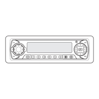
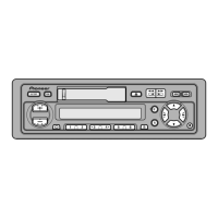
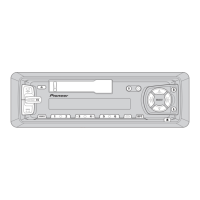
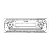
Diagram and parts list for the external assembly of the unit.

2.2 Cassette Mechanism Module

Diagram and parts list for the cassette transport mechanism.

3. Block Diagram and Schematic Diagram

3.1 Block Diagram

High-level functional overview of the system's architecture.

3.2 Overall Connection Diagram(Guide Page)

Diagram showing major interconnections between system components.

3.3 Keyboard Unit

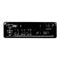
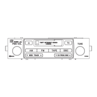
Schematic or layout for the user interface keyboard assembly.

3.4 Cassette Mechanism Module

Schematic or layout for the cassette transport mechanism.

4. PCB Connection Diagram

4.1 Main Unit

Layout and connector details for the main printed circuit board.

4.2 Keyboard Unit(KEX-M8547ZT/EW)

PCB layout for the keyboard unit of model KEX-M8547ZT/EW.

4.3 Keyboard Unit(KEX-M8647ZT/EW)

PCB layout for the keyboard unit of model KEX-M8647ZT/EW.

4.4 Cassette Mechanism Module

PCB layout for the cassette mechanism module assembly.

5. Electrical Parts List

6. Adjustment

6.1 Jig Connection Diagram

Diagram detailing connections for adjustment jigs.

6.2 Cassette and Audio Adjustment

Procedures for adjusting cassette and audio performance.

6.3 Self-Diagnosis Function

Instructions for performing self-diagnostic checks.

AM Noise Canceler Adjustment

Diagnosis Code Table

7. General Information

7.1 Diagnosis

Information related to system diagnosis and troubleshooting.

7.2 IC

Detailed pin functions for integrated circuits used in the unit.

7.3 Explanation

Overview of system operation and block diagrams.

7.4 Cleaning

Instructions for cleaning specific parts before shipping.

8. Operations

Jigs List

Related product manuals