Do you have a question about the Pioneer MVH-S100UB/XINEW5 and is the answer not in the manual?
| Category | Receiver |
|---|---|
| Model | MVH-S100UB/XINEW5 |
| Brand | Pioneer |
| DIN Size | 1 DIN |
| Tuner | FM/AM |
| USB Input | Yes |
| Bluetooth | No |
| Display Type | LCD |
| AUX Input | Yes |
| Subwoofer Preamp Output | Yes |
| MP3 Playback | Yes |
| WMA Playback | Yes |
| FLAC Playback | No |
| Android Compatibility | Yes |
| Detachable Face | Yes |
| Dimensions | 178 x 50 x 165 mm |
| Power Output | 50W x 4 |
| Peak Power Output | 50 Watts x 4 |
| Preamp Voltage | 2V |
General safety guidelines for servicing the unit.
Important notes before and during unit disassembly and reassembly.
Guidelines for handling and replacing electronic components safely.
Additional notes related to soldering and securing the front panel.
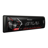
Lists main product specifications, referring to the Owner's Manual for details.
Essential checks to ensure product quality and customer satisfaction post-service.
Visual representation of the unit's internal components and their interconnections.
Illustrates the power distribution and voltage rails within the unit.
Step-by-step troubleshooting guide for initial power-on and source operation.
Mode to test LCD and grille illumination, checking various display patterns.
Step-by-step instructions for removing the front panel assembly.
Instructions for detaching the tuner amplifier assembly from the chassis.
Steps to remove the tuner amplifier unit itself.
Detailed steps for disassembling the panel components.
Detailed steps for reassembling the panel components.
Indicates that no specific setting or adjustment procedures are detailed in this chapter.
Exploded view and parts list for the packaging and accessories.
Exploded view detailing the external components and their arrangement.
Detailed circuit diagram for the tuner amplifier unit.
Detailed circuit diagram for the keyboard unit.
Diagram showing PCB layout and connector pin assignments for the tuner amp unit.
Diagram showing PCB layout and connector pin assignments for the keyboard unit.
Comprehensive list of electrical components with their respective part numbers.