PDP-5000EX
78
1234
1234
C
D
F
A
B
E
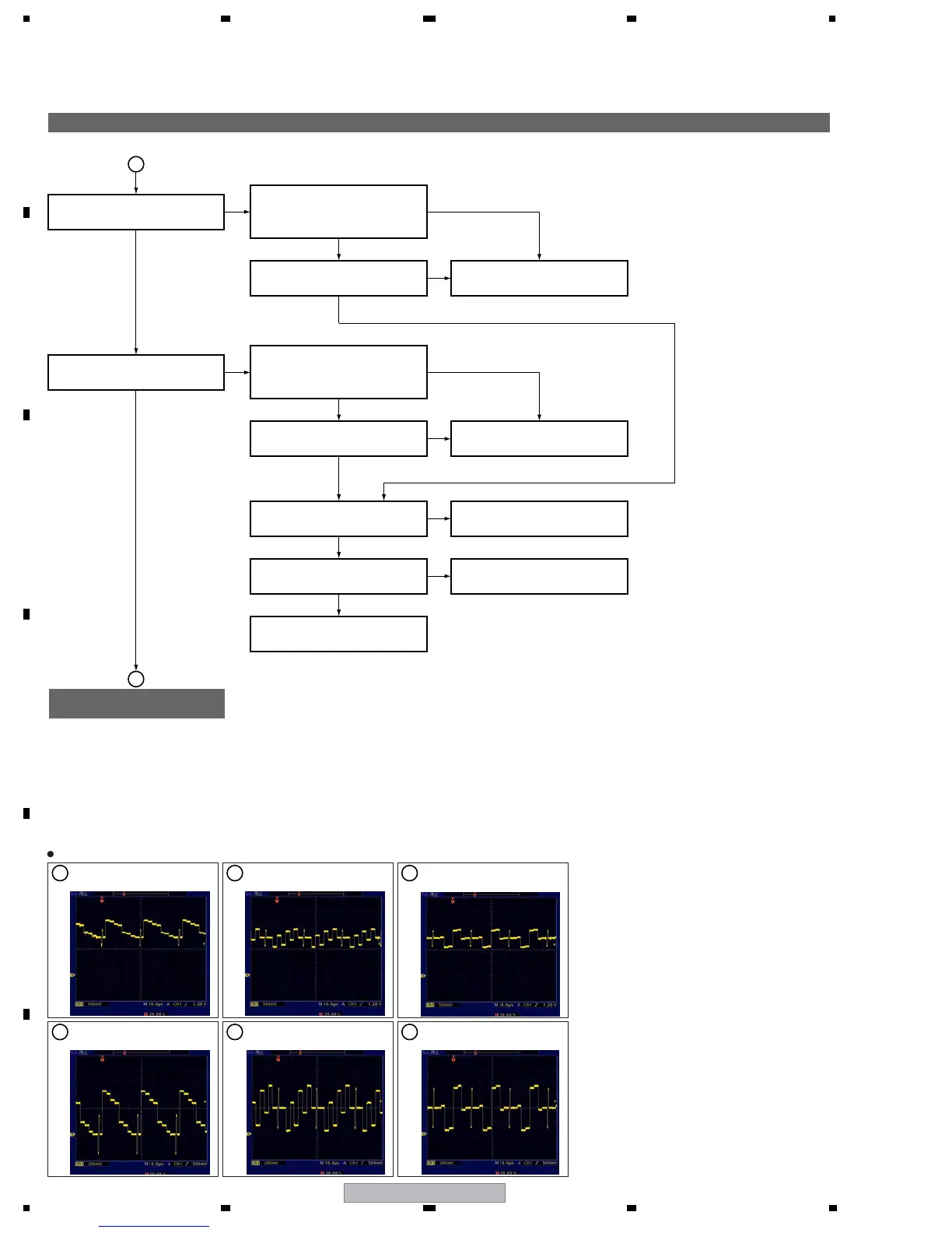
Flowchart of Failure Analysis for The MAIN Assy (3)
Flowchart of Failure Analysis
for The MAIN Assy (4)
Is the signal output from IC5601?
(pin 34, 32, 54)
(Waveforms 9, 0, -)
Is the signal input to IC5202?
(pin 48, 43, 54)
(Waveforms =, ~, !)
No
Yes
Yes
Yes
Yes
Yes
No
Is the selected input signal an
analog component signal?
Is the selected input signal an
analog RGB signal?
Yes
Yes
Replace the MAIN Assy.
Failure in the line between the JA5201 and IC5601.
Are the displayed on the
"SG MODE: ANA AD YCBCR"
of the Factory menu correct?
Are the displayed on the
"SG MODE: ANA AD RGB"
of the Factory menu correct?
Is the signal input to IC5601?
(pin 70, 72, 74)
Is the signal input to IC5601?
(pin 2, 4, 6, 14, 15)
No
Replace the MAIN Assy.
Failure in the line between the JA5201 and IC5601.
No
Replace the MAIN Assy.
IC5601 and its peripheral circuits are in failure.
No
Replace the MAIN Assy.
Failure in the line between the IC5601 and IC5202.
Replace the MAIN Assy.
IC5202 and its peripheral circuits are in failure.
No
Yes
No
No
B
A
9
IC5601 - pin 34
V: 500 mV/div H: 10 µsec/div
IC5601 - pin 32
V: 500 mV/div H: 10 µsec/div
10
141312
11
IC5601 - pin 30
V: 500 mV/div H: 10 µsec/div
IC5202 - pin 48
V: 200 mV/div H: 10 µsec/div
IC5202 - pin 43
V: 200 mV/div H: 10 µsec/div
IC5202 - pin 54
V: 100 mV/div H: 10 µsec/div
Waveforms

 Loading...