EasyManua.ls Logo

Pioneer VSX-09TX User Manual

Pioneer VSX-09TX
84 pages
To Next Page IconTo Next Page
Page #1 background imageLoading...
Page #1 background image
Q I IO Wa ~ W
er vice
anua
=--: G(G)
ORDER NO.
R RV1 7 7 0
AUDIOIVIDEO STEREO RECEIVER
VSX-07TX
VSX-09TX
THIS MANUAL IS APPLICABLE TO THE FOLLOWING MODEL(S) AND TYPE(S).
Model
Type Power Requirement
The voltage can be converted by the
YSX-DBOBS
VSX4 7TX VSXMTX
following method.
KU AC120V
KC AC120V
SD AC110V/1 20 1 27V/220Vi240V With the volta e selector
KU/CA AC120V
CONTENTS
1. SAFETY INFORMATION .
2. EXPLODED VIEWS AND PARTS LIST ............
2 3
3. SCHEMATIC DIAGRAM 12
4. PCB CONNECTION DIAGRAM ....................... 49
5. PCB PARTS LIST .. 80
6. ADJUSTMENT 93
7. GENERAL INFORMATION.
7.1 PARTS
96
7.1. 1 IC ...................................................
7.1.2 DISPLAY . 100
7.2 BLOCK DIAGRAM . . 102
7.3 REMOTE CONTROL UNIT....................... ... 104
8. PANEL FACILITIES AND SPECIFICATIONS ... ... 108
PIONEER ELECTRONIC CORPORATION 4-1, Meguro 1-chome, Meguro-ku, Tokvo153, Japan
PIONEER ELECTRONICS SERVICE. INC. PO.Box 1760, Long Beach, CA 90801-1760, U.S.A.
PIONEER ELECTRONIC [EUROPEI N.V. Haven 1087, Keetberglaan 1, 9120 Melsele. Belgium
PIONEER ELECTRONICS ASIACENTRE PTE. LTO. 501 Orchard Road, ff10-00 Lans Cra wf ord Place, Singapore 0923
© PIONEER ELECTRONIC CORPORATION 1997 T-FZK MAY 1997 Printed in Belgium
All manuals and user guides at all-guides.com
all-guides.com
Question and Answer IconNeed help?

Do you have a question about the Pioneer VSX-09TX and is the answer not in the manual?

Pioneer VSX-09TX Specifications

General IconGeneral
TypeStereo Receiver
Total Harmonic Distortion0.08%
Input Sensitivity200 mV
Signal to Noise Ratio100 dB
Video InputsComposite, S-Video
Power Output100 Watts per channel
Frequency Response5Hz to 100kHz
Digital InputsCoaxial, Optical
Surround Sound FormatsDolby Digital, DTS
Speaker Load Impedance8Ω to 16Ω

Summary

Safety Information

Safety Precautions and Leakage Current Check

Covers safety precautions, leakage current checks, and product safety notices.

Exploded Views and Parts Lists

Component Identification and Assembly Views

Lists parts, numbers, and variations across models, including packing details.

Exterior and Sectional Views

Visual breakdowns of exterior, radiator, and front panel components for assembly.

Schematic Diagrams

Overall Connection Diagram

Shows the main signal flow and connections between major internal assemblies.

Audio Signal Path Schematics

Details circuitry for the audio signal path.

Video Signal Path Schematics

Details circuitry for the video signal path.

Power Supply and Tuner Schematics

Illustrates power supply, tuner, and interface circuitry schematics.

PCB Connection Diagrams

PCB Layouts for Signal Assemblies

Shows physical component placement and connections on specific PCB assemblies for service.

PCB Parts List

Comprehensive Component Lists for PCB Assemblies

Comprehensive list of all PCB assemblies and their corresponding part numbers for replacement.

Adjustment Procedures

Tuner and Idle Current Adjustments

Step-by-step guides for tuning FM/AM sections and setting amplifier idle current.

General Information and Remote Control

Parts, Block Diagram, and IC Pinouts

Details IC pinouts, block diagrams, and general parts information.

Remote Control Unit Operation Details

Exploded views, parts lists, and schematic for the remote control unit, including button functions.

Panel Facilities and Specifications

Front Panel Controls and Connectivity

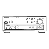
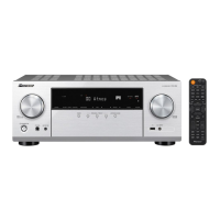
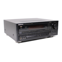
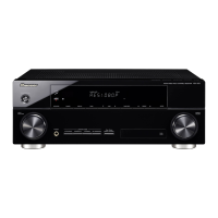
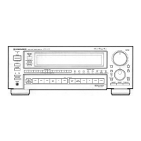
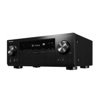
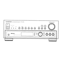
Identifies front panel controls, connectivity options, and speaker system setup.

Technical Specifications

Detailed performance specifications for amplifier, tuner, video, and other sections of the receiver.

Related product manuals