Do you have a question about the Pioneer VSX-79 and is the answer not in the manual?
General safety guidelines, leakage current check, and component safety notes.
Comprehensive schematic diagram of the unit's circuitry.
Step-by-step guide for removing PCB assemblies from the unit.
Procedures for adjusting tuner sensitivity, VCO, and stereo distortion.
Adjustments for idle current and GUI screen display position.
Block diagram illustrating the microcomputer control section.
Block diagram detailing the audio and video signal flow.
| Power Output | 100 watts per channel into 8Ω (stereo) |
|---|---|
| Frequency Response | 5Hz to 100kHz |
| Total Harmonic Distortion | 0.06% |
| Dimensions | 420 x 158 x 352.5mm |
| Weight | 8.6kg |
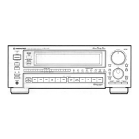
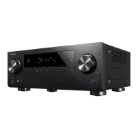
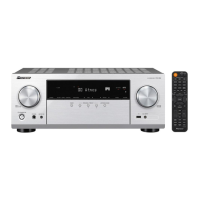
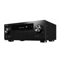
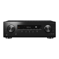
| Type | AV Receiver |
| HDMI | Yes |
| Input Sensitivity | 200mV (line) |