EasyManua.ls Logo

Pioneer xR-P740 User Manual

Pioneer xR-P740
63 pages
To Next Page IconTo Next Page
Page #1 background imageLoading...
Page #1 background image
Service
Manual
/oo.
^
-5
-8
-9
(v)
proNeerl"
Tlp
Art
ot Entertaiment
STEREO
MULTI-PLAY
CD
CASSETTE
DECK
RECEIVER
x
x
R.P7
-P64olul
-P34()M
4()M
CD
CASSETTE
DECK
RECEIVER
ORDER NO.
RRV1O23
R
R
r;
o
o
o
4
4
4
7
6
3
P
P
P
I
I
I
STEREO
XR
XR
XR
r
CONTENTS
CHAPTER
1
1.8 PARTS
LIST
FOR PACKING
AND
EXPLODED
VTEWS
... .......
..............
1
-
38
1.9
PCB PARTS
LIST
...
1-47
CHAPTER
2
2.1
PACKING
AND EXPLODED
VIEWS
, .
2-2
2.2
SCHEMATIC
AND
PCB CONNECTION
DfAGRAMS
.........2-16
-tl
-20
6
_EB
q
_f__l:i
io
:tr)lo6a-
o6tb
.68
it
a5
THIS
MANUAL
IS
APPLICABLE
TO
THE FOLLOWING
IVIODEL(SI
AND TYPE(S}.
Typ.
Modol
Powor
Roquhemant
Tha vohago
cln ba
convanod
by lh. folowlng
m.thod.
xR-P740M
xR-P740
xR-P640M
XR-P6/|{)
xR-P3/l(,M
xR'P340
SD
o
o
o
o
o
o
AC110V
t120-
127V
I
220V
t240V
With the
voltago solector
o
o
o o
AC240V
KU
o
AC120V
KC
o
AC120V
PIONEER
ELECTRONIC
CORPORATION
4,j, Mesuro
I chome, Mesuro
ku, rokyo 1s3
Japan
PIONEER
ELECTRONICS
SERVTCE lNC.
pO
Box 1760,
Long
Bea;h, CatrJornra
90801 U.S.A.
PDNEERELECTROI{ICSOFCANAOA,tNC.3O0A
slareparkwayN.4arkham,OntanoL3BOp2Canada
PIONEER
ELECTROT{IC
[EUROPE]
N.V Haven
jO87
Keetberataan
t,9j2O Met;ete.
Betorurn
PIoNEEB
ELEcrRoNlcs
AusrBALla Pw.
LTD. r78 r84
Boundary
ioad
B aesroe. vr.fo.ra
3195
Ausrra
a
TLL
o P|oNEER
ELECTRONTC
CORPORATTON
1993.
r DFF
[03]
580,99r1
DEC. 1993
Printed
in
Japan
Question and Answer IconNeed help?

Do you have a question about the Pioneer xR-P740 and is the answer not in the manual?

Pioneer xR-P740 Specifications

General IconGeneral
CategoryCar Receiver
BrandPioneer
ModelXR-P740
Channels4
Built-in BluetoothNo
AUX InputYes
CD PlayerYes
AM/FM TunerYes
Display TypeLCD
Remote ControlYes

Summary

Chapter 1: System Overview and Maintenance

Safety Information

Essential safety guidelines, warnings, and product safety notices for service technicians.

Specifications

Detailed specifications for amplifier, tuner, cassette, and CD sections of the receiver.

Panel Facilities

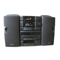
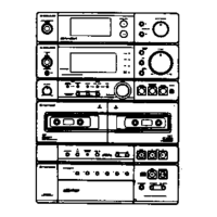
Identification and description of front panel controls, buttons, and indicators on the receiver.

Disassembly

Procedures for disassembling unit components like the CD mecha and AF CD Assy.

Block Diagram

Block diagrams illustrating the overall system architecture and power amp module sections.

IC Information

Detailed pin assignments and functions for key integrated circuits used in the system.

Adjustments

Step-by-step instructions for tuning, power amp, cassette, and CD section adjustments.

Parts List for Packing and Exploded Views

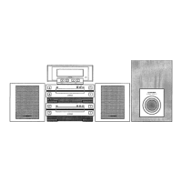
Lists of parts for packing, exploded views of exterior components, and cassette mecha.

PCB Parts List

Comprehensive list of PCB assemblies and their part numbers for various sections of the unit.

Related product manuals