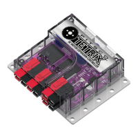
Motor1_Target: Sending the command byte 0x46 puts motor channel 1 in encoder count targeting mode. Six data bytes
set the speed and encoder target value for motor channel 1. The first two data bytes represent the speed parameter in
degrees per second. The last four data bytes represent the encoder 1 target count value. The motor controller firmware
will assemble the first and second bytes into a 16-bit signed integer representing the Motor 1 speed parameter with the
first byte being the High byte. Each speed parameter range is -32,768 to 32,767. The last four bytes represent the encoder
1 target value, which gets assembled into a 64-bit signed long integer with the High byte transmitted first. Each encoder
target value range is -2,147,483,648 to 2,147,483,647. Negative speed values will be ignored. Motor 1 will run at the set
values governed by a PID algorithm at a constant speed until the encoder target is reached and then hold position in a
servo-like mode.
Motor2_Target: Sending the command byte 0x47 puts motor channel 2 in encoder count targeting mode. Six data bytes
set the speed and encoder target value for motor channel 2. The first two data bytes represent the speed parameter in
degrees per second. The last four data bytes represent the encoder 2 target count value. The motor controller firmware
will assemble the first and second bytes into a 16-bit signed integer representing the Motor 2 speed parameter with the
first byte being the High byte. Each speed parameter range is -32,768 to 32,767. The last four bytes represent the encoder
2 target value, which gets assembled into a 64-bit signed long integer with the High byte transmitted first. Each encoder
target value range is -2,147,483,648 to 2,147,483,647. Negative speed values will be ignored. Motor 2 will run at the set
values governed by a PID algorithm at a constant speed until the encoder target is reached and then hold position in a
servo-like mode.
Motor_Targets: Sending the command byte 0x48 puts both motor channels in encoder count targeting mode. Twelve
data bytes set the speed and encoder target values for Motor 1 and Motor 2 simultaneously. Bytes 1 and 2 represent the
speed parameter in degrees per second for Motor 1. Bytes 3, 4, 5, and 6 represent the encoder 1 target count value. Bytes
7 and 8 represent the speed parameter in degrees per second for Motor 2. The remaining four data bytes represent the
encoder 2 target count value. All value parameters are transmitted with the High byte first. The motor controller firmware
will assemble the speed value parameters for Motor 1 and 2 into two 16-bit signed integers. Each speed parameter range
is -32,768 to 32,767. The target value parameters are each four bytes long, which the firmware will assemble into two
64-bit signed long integers each with the High byte transmitted first. Each encoder target value range is -2,147,483,648 to
2,147,483,647. Negative speed values will be ignored. Motors 1 and 2 will run at the set values governed by a PID algorithm
at a constant speed until the encoder target is reached and then hold position in a servo-like mode.
Motor1_Degree: Sending the command byte 0x58 puts motor channel 1 in encoder degrees targeting mode. Six data
bytes set the speed and encoder target in degrees of rotation for motor channel 1. The first two data bytes represent the
speed parameter in degrees per second. The last four data bytes represent the encoder 1 target degree value. The motor
controller firmware will assemble the first and second bytes into a 16-bit signed integer representing the Motor 1 speed
parameter with the first byte being the High byte. Each speed parameter range is -32,768 to 32,767. The last four bytes
represent the encoder 1 target degree value, which gets assembled into a 64-bit signed long integer with the High byte
transmitted first. Each encoder target degree value range is -536,870,912 to 536,870,911. Negative speed values will be
ignored. Motor 1 will run at the set values governed by a PID algorithm at a constant speed until the encoder degree target
is reached and then hold position in a servo-like mode.
Motor2_Degree: Sending the command byte 0x59 puts motor channel 2 in encoder degrees targeting mode. Six data
bytes set the speed and encoder target in degrees of rotation for motor channel 2. The first two data bytes represent the
speed parameter in degrees per second. The last four data bytes represent the encoder 2 target degree value. The motor
controller firmware will assemble the first and second bytes into a 16-bit signed integer representing the Motor 2 speed
parameter with the first byte being the High byte. Each speed parameter range is -32,768 to 32,767. The last four bytes
represent the encoder 2 target degree value, which gets assembled into a 64-bit signed long integer with the High byte
transmitted first. Each encoder target degree value range is -536,870,912 to 536,870,911. Negative speed values will be
ignored. Motor 2 will run at the set values governed by a PID algorithm at a constant speed until the encoder degree target
is reached and then hold position in a servo-like mode.
Motor_Degrees: Sending the command byte 0x5A puts both motor channels in encoder degrees targeting mode. Twelve
data bytes set the speed and encoder degree target values for Motor 1 and Motor 2 simultaneously. Bytes 1 and 2 represent
the speed parameter in degrees per second for Motor 1. Bytes 3, 4, 5, and 6 represent the encoder 1 target degree value.
Bytes 7 and 8 represent the speed parameter in degrees per second for Motor 2. The remaining four data bytes represent
the encoder 2 target degree value. All value parameters are transmitted with the High byte first. The motor controller
firmware will assemble the speed value parameters for Motors 1 and 2 into two 16-bit signed integers. Each speed
parameter range is -32,768 to 32,767. The target degree value parameters are each four bytes long, which the firmware
will assemble into two 64-bit signed long integers each with the High byte transmitted first. Each encoder target degree
value range is -536,870,912 to 536,870,911. Negative speed values will be ignored. Motors 1 and 2 will run at the set values
governed by a PID algorithm at a constant speed until the encoder degree target is reached and then hold position in a
servo-like mode.
 Loading...