ITEM 93645
PLEASE READ THE FOLLOWING CAREFULLY
THE MANUFACTURER AND/OR DISTRIBUTOR HAS
PROVIDED THE PARTS DIAGRAM IN THIS MANUAL
AS A REFERENCE TOOL ONLY. NEITHER THE
MANUFACTURER NOR DISTRIBUTOR MAKES ANY
REPRESENTATION OR WARRANTY OF ANY KIND TO
THE BUYER THAT HE OR SHE IS QUALIFIED TO
MAKE ANY REPAIRS TO THE PRODUCT OR THAT
HE OR SHE IS QUALIFIED TO REPLACE ANY PARTS
OF THE PRODUCT. IN FACT, THE MANUFACTURER
AND/OR DISTRIBUTOR EXPRESSLY STATES THAT
ALL REPAIRS AND PARTS REPLACEMENTS
SHOULD BE UNDERTAKEN BY CERTIFIED AND LI-
CENSED TECHNICIANS AND NOT BY THE BUYER.
THE BUYER ASSUMES ALL RISK AND LIABILITY
ARISING OUT OF HIS OR HER REPAIRS TO THE
ORIGINAL PRODUCT OR REPLACEMENT PARTS
THERETO, OR ARISING OUT OF HIS OR HER IN-
STALLATION OF REPLACEMENT PARTS THERETO.
Operation
(Refer to the diagram to the right and the picture on the front.)
1. Attach the chosen Socket (1a-1d) to the Output Driver (7).
Note: The Output Driver (7) is on the side of the Housing (4)
that has no screw heads visible.
2. Attach the Support Socket and Knob (2,3) through the slot in the
housing, with the Support Socket (2) on the same side as the
Socket (1a). Leave the Knob (3) loose.
3. Raise the vehicle, support the vehicle on jackstands (not included),
engage the parking brake, and place wheel chocks (not included)
on any wheels contacting the ground. Place the Socket (1a) over
the Lugnut that will be tightened or loosened and place the Support
Socket (2) over another Lugnut on the same rim. The Socket
may need to be repositioned and/or the Input Driver (13) may
need to be turned to get both sockets securely in place. Tighten
the Support Knob (3).
WARNING: Make certain that both Sockets are securely in
place over the Lugnuts.
4. Place the Handle Shaft (16) over the Input Driver (13) unfold the Handle (18) and turn it in the direction noted on
the Gearbox Cover (15). NOTE: This will be the opposite of the normal tightening/loosening direction.
The Handle (18) should move relatively easily - if it does not, the unit may be assembled backwards, check step
one above to ensure that the Socket is on the Output Driver (7). Keep in mind that the socket will move slowly,
this is by design.
5. When tightening, finger tighten the lugnut first. Keep in mind that this device allows you to apply much more
torque than you ordinarily could. Use care not to overtighten lugnuts.
6. After use, disassemble, clean, and store in Carrying Case (19).
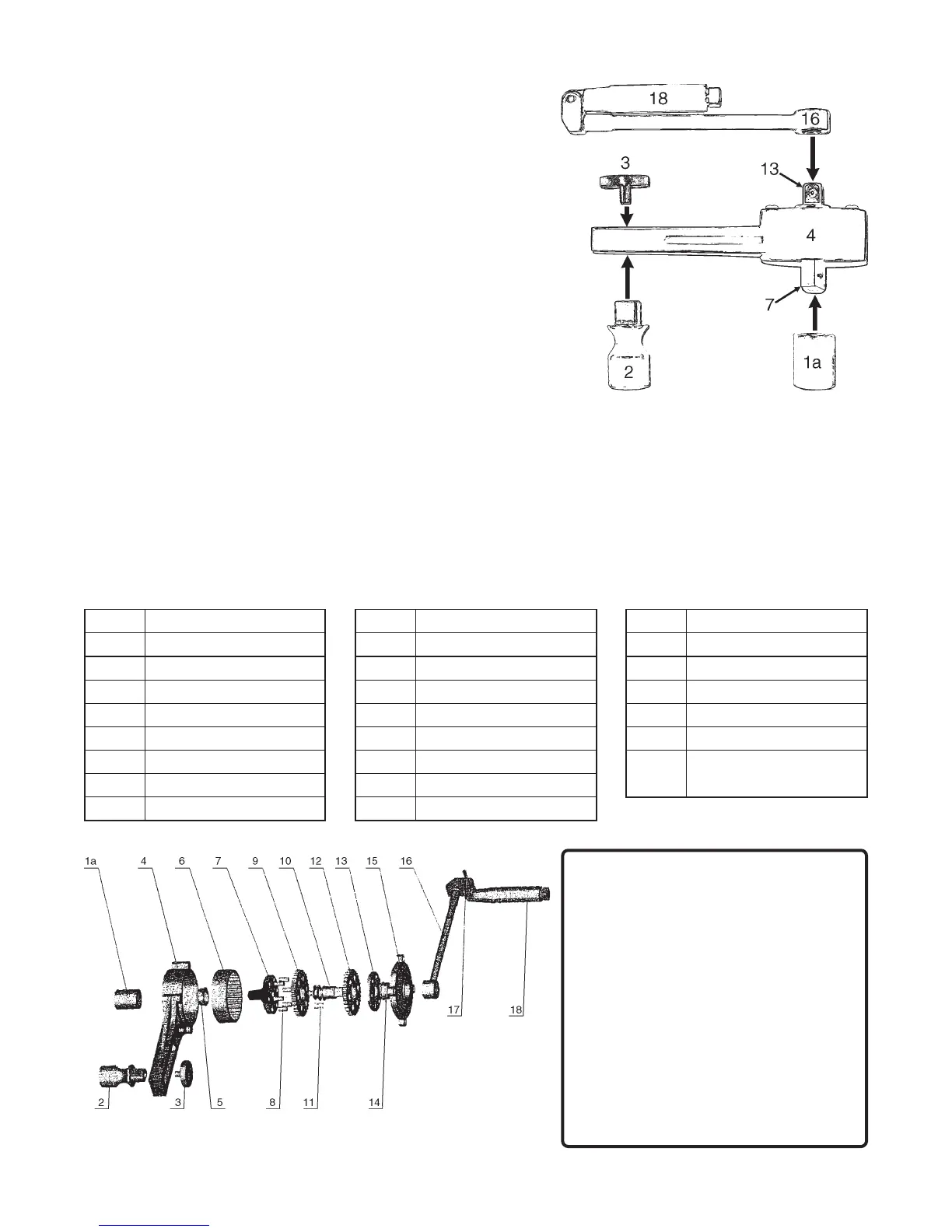
Assembly Diagram
NOTE: Some parts are listed and shown for illustration purposes only
and are not available individually as replacement parts.
Parts List
traPnoitpircseDtraPnoitpircseDtraPnoitpircseD
a1tekcoSmm916raeGsulunnAretuO41gniraeB
b1tekcoS"4/37revirDtuptuO51revoCx
obraeG
c1tekcoS"61/318niP61tfahSeldnaH
d1tekcoS"8/79raeGsulunnArennI71niPeldnaH
2tekcoStroppuS01gnihsuBcirtneccE81eldna
H
3bonKtroppuS11niP
91
esaCgniyrraC
)nwohStoN(
4gnisuoH21raeGsulunnArennI
5gniraeB31revirDtupnI
 Loading...