F300-14-00 2 I56-035-00R
©2000 Fire•Lite
B. Smoke Entry: Aerosol Generator (Gemini 501)
The GEMINI model 501 aerosol generator can be used for smoke entry testing. Set the generator to represent 4%/ft to 5%/ft obscuration as described in
the GEMINI 501 manual. Using the bowl shaped applicator, apply aerosol until the panel alarms.
C. Direct Heat Method (Hair dryer of 1000-1500 watts). SD350T only.
Direct the heat toward either of the side thermistors. Hold the heat source about 12 inches from the detector in order to avoid damage to the plastic. The
detector will reset only after it has had sufficient time to cool.
Both smoke and heat detection testing are recommended for verifying system protection capability.
A sensor that fails any of these tests should be cleaned as described under CLEANING, and retested. If the sensor fails after cleaning, it must be replaced
and returned for repair.
When testing is complete, restore the system to normal operation and notify the proper authorities that the system is back in operation.
CLEANING
It is recommended that the detector be removed from its mounting base to facilitate cleaning. The detector is cleaned as follows:
NOTE: Before removing the detector, notify the proper authorities that the smoke detector system is undergoing maintenance and will be temporarily out
of service. Disable the zone or system undergoing maintenance to prevent unwanted alarms.
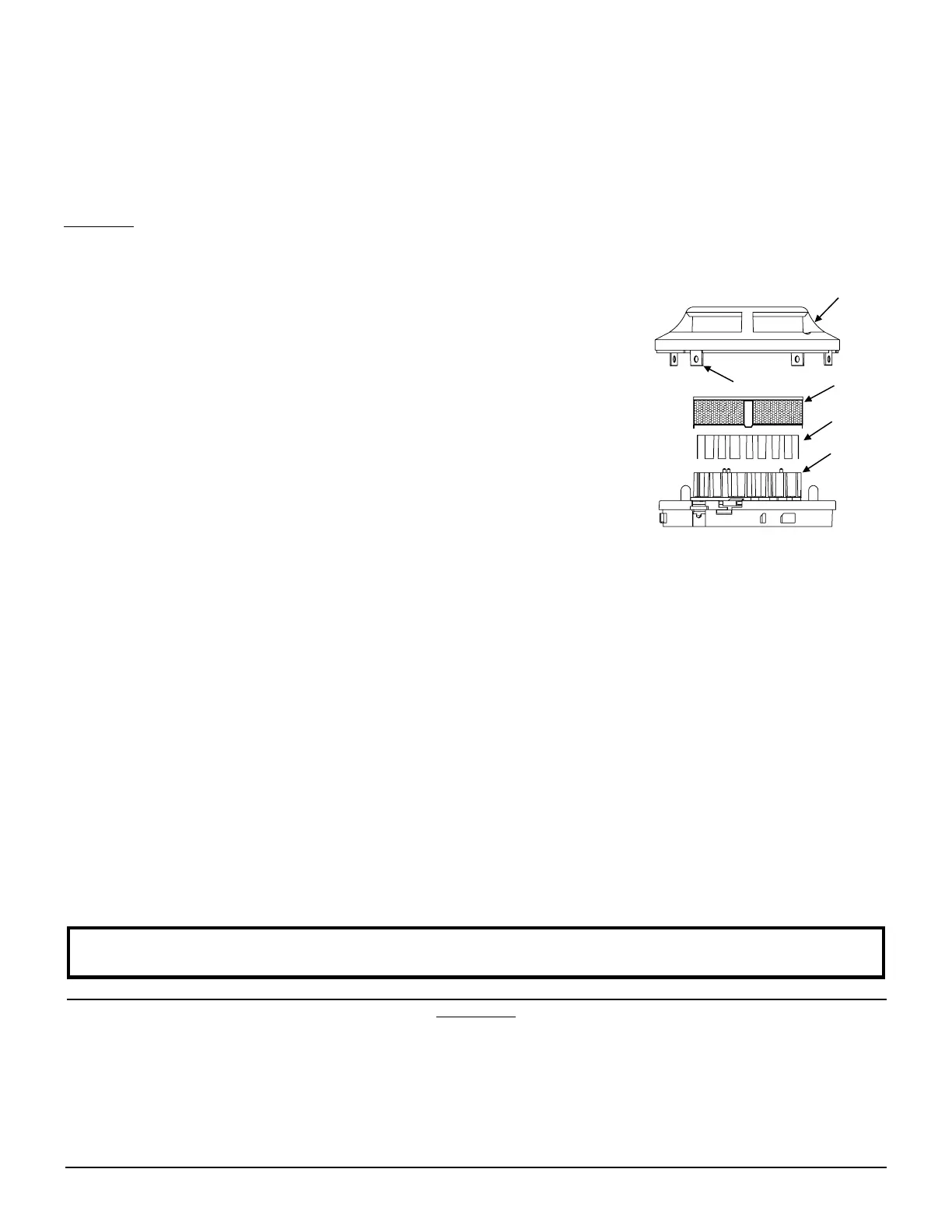
1. Remove the detector cover by prying away the four side tabs with a small-bladed screwdriver, and then
pulling the cover from the base.
2. Vacuum the screen carefully without removing it. If further cleaning is required continue with Step 3,
otherwise skip to Step 8.
3. Remove the screen assembly by pulling it straight out (see Figure 4).
4. Remove the sensing chamber cover by pulling it straight out.
5. Clean the vaned chamber piece by vacuuming or blowing out dust and particles.
6. Replace the sensing chamber cover, aligning the arrow on the top with arrow on the printed circuit board.
7. To replace the screen, place it over the chamber assembly, turning it until it snaps into place.
8. Replace the cover using the LEDs to align the cover and then gently pushing it until it locks into place.
9. Reinstall the detector.
10. Test the detector as described in TESTING.
11. Reconnect disabled circuits.
12. Notify the proper authorities that the system is back on line.
A78-2463-08
Figure 4.
FCC Statement
This device complies with part 15 of the FCC Rules. Operation is subject to the following two conditions: (1) This device may not cause harmful interference, and (2) this
device must accept any interference received, including interference that may cause undesired operation.
Note: This equipment has been tested and found to comply with the limits for a Class B digital device, pursuant to Part 15 of the FCC Rules. These limits are designed
to provide reasonable protection against harmful interference in a residential installation. This equipment generates, uses and can radiate radio frequency energy and,
if not installed and used in accordance with the instructions, may cause harmful interference to radio communications. However, there is no guarantee that interference
will not occur in a particular installation. If this equipment does cause harmful interference to radio or television reception, which can be determined by turning the
equipment off and on, the user is encouraged to try to correct the interference by one or more of the following measures:
– Reorient or relocate the receiving antenna.
– Increase the separation between the equipment and receiver.
– Connect the equipment into an outlet on a circuit different from that to which the receiver is connected.
– Consult the dealer or an experienced radio/TV technician for help.
SENSOR
COVER
SENSING
CHAMBER
SENSING
CHAMBER
COVER
SENSOR
SCREEN
COVER REMOVAL
TABS
Please refer to insert for the Limitations of Fire Alarm Systems
 Loading...