D500-02-00 3 I56-309-03
NOTE: If the sensor’s sensitivity limits or the MOD400R limits do not appear on the back of the sensor, the MOD400R is
not suitable for field sensitivity testing of that unit.
PAINTED
SURFACE
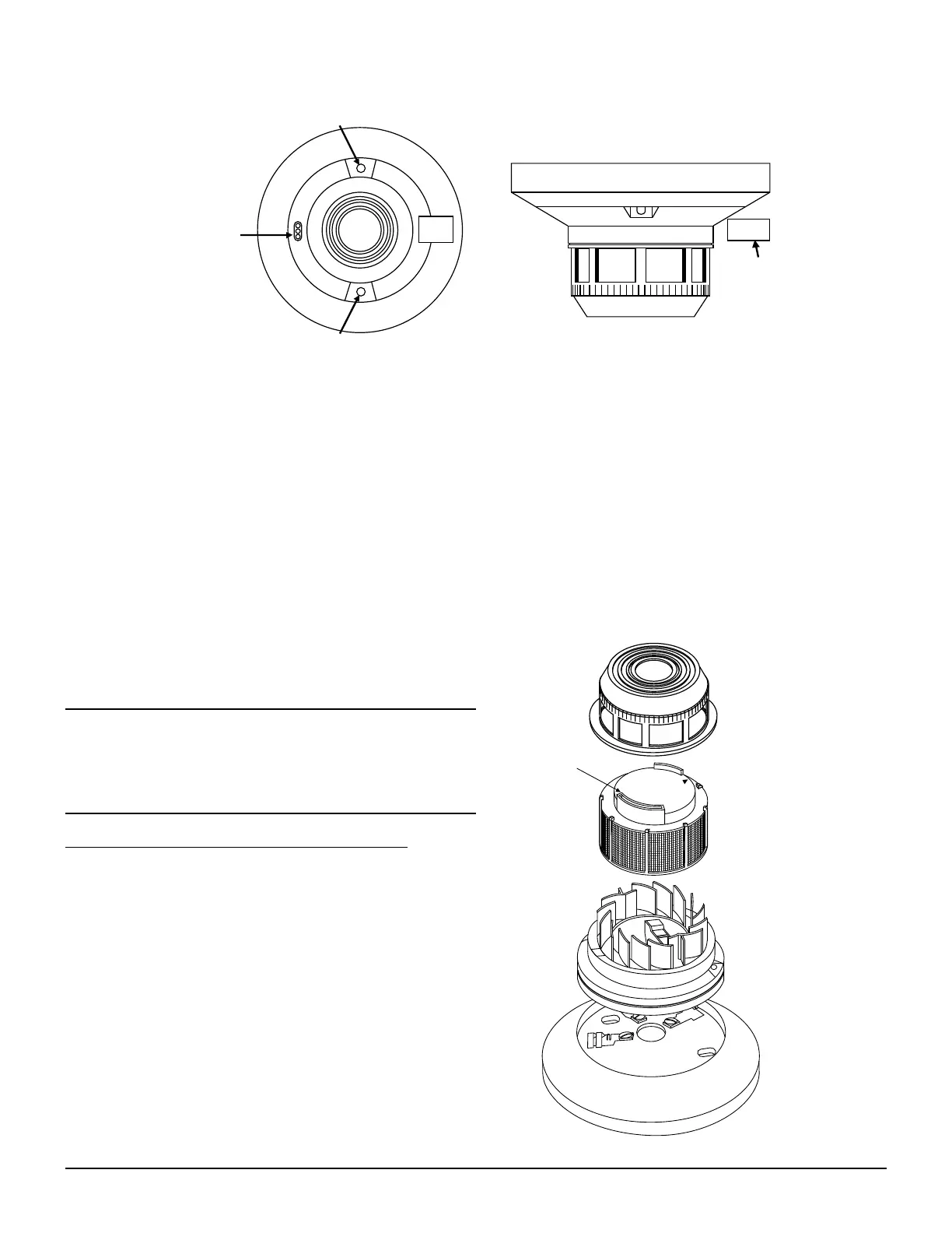
TEST
MAGNET
TEST MODULE
SOCKET
LED
LED
TEST
MAGNET
A78-1977-00
Figure 2. Views showing position of test magnet
C. Aerosol Generator (Gemini 501) per NFPA 72
The field test tool is the Gemini Model 510 aerosol generator. Set the generator to represent 4%/ft to 5%/ft obscuration
as described in the Gemini 501 manual. Using the bowl shaped applicator, apply aerosol until unit alarms.
D. Direct Heat Method (Hair dryer of 1000-1500 watts)
Direct the heat toward the thermal collector, holding the heat source about 12 inches away from the detector to avoid
damage to the plastic. The detector will reset only after the collector has had sufficient time to cool and the power
source has been momentarily interrupted.
NOTE: This test only verifies proper operation of the sensor and is not used to test sensitivity.
After testing, detectors must be reset from the control panel. Notify the proper authorities that the system is back on line.
Sensors that fail these tests should be cleaned as described
under CLEANING and retested. If the sensors still fail these
tests they should be returned for repair.
CAUTION
A dust cover is not a substitute for removing sensor during
new construction or heavy remodeling. Cover only helps
limit dust entry.
CLEANING THE SDX-551/SDX-551TH SENSOR
NOTE: Before cleaning, notify the proper authorities that
the smoke sensor system is undergoing mainte-
nance and will temporarily be out of service. Disable
the loop or system undergoing maintenance to pre-
vent unwanted alarms.
It is recommended that the sensor be removed from its
mounting base to facilitate easier cleaning. See Figure 3.
The sensor is cleaned as follows:
1. Remove the sensor cover by placing a small bladed
screwdriver in the side slot of the sensor cover, twisting it
slightly until the cover can be turned counterclockwise for
removal.
REMOVABLE COVER
REMOVABLE SCREEN
P/N RS24 (W/O THERMAL)
RS24T (W/THERMAL
TEST SLOT
A78-1941-01
Figure 3
www.PDF-Zoo.com
 Loading...