4
Troubleshooting
Fixture remains at blackout when illumination expected
• The
indicator should be lit - if not, check the
input power and fuse (see below).
• If live DMX is connected, the
indicator should
be lit - if not, check the DMX cable and the desk output.
• Check that the selected
MODE matches the desk per-
sonality being used.
• The master intensity channel for the current mode may
be set at zero. For
DMX mode, check the setting of
PERS
>
MINT.
• Ensure that only one DMX device in the chain is set as
master.
• Standalone chase effects: Effects programmed using
PROG
>
C1 and C2 but the fixture is not in MODE
>
EF M mode. Check also that PROG
>
LEVL is not
set at zero.
• Standalone RGB mixing: Colour values set within
MAN
section but the fixture is not in MODE
>
MANU mode.
Unexpected cell illumination occurring
• When using
DMX mode: Check the setting of PERS >
RES. See the section “DMX channel and cell layouts”
on page 2 for an explanation of the various resolution
modes.
Fuse access
The single fuse is located next to the power and DMX
input connectors. Use a small flat blade screw driver to
twist the fuse holder anticlockwise until the carrier can be
extracted to reveal the fuse.
Weight
Fixture alone: 10.5kg (23 lbs)
With combi yoke: 11.7kg (25.8 lbs)
Power
Input voltage: 90 to 264V AC, 47 to 63Hz autosensing
Earth leakage 1.61mA
Connectors: 16 amp CEE Form 2Pole+Earth (input & output)
Power requirements: @ 230V/50Hz @ 115V/60Hz
Standby 20 watts 20 watts
Maximum (const.) 300 watts 300 watts
Start up (peak*) 128 amps 64 amps
* The peak value occurs only at first power up and
lasts only for a period measured in microseconds.
Adjustments may need to be made to supply circuit
breakers when multiple fixtures are daisy-chained,
causing them all to draw the peak simultaneously.
Approvals
Miscellaneous
Enclosure rating: IP20 (not protected against moisture ingress)
Control input: USITT DMX512 (input connector pin out below)
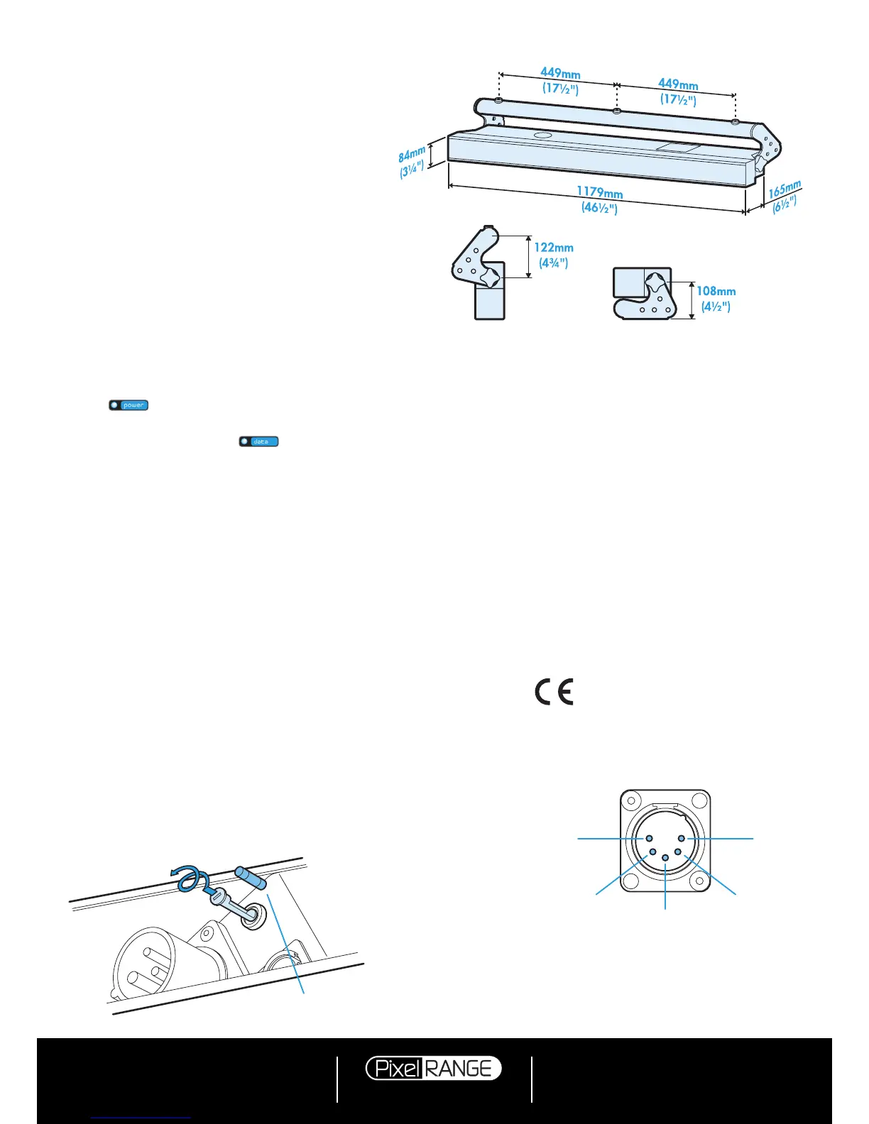
Specifications
Dimensions
Fuse type: 20mm 4A (T4AH)
anti-surge, ceramic body
PIN 1
Ground
PIN 2
Data
–
PIN 3
Data +
PIN 5
Not used
PIN 4
Not used
Documentation by Corporate Text & Design (www.ctxd.com)
Release 1.02b
Using master mode to drive other units
This unit can control any number of other Pixel Range
fixtures via DMX links, without the need for a control desk.
1 Set this unit as
master (PERS > DATA > MAST) and
ensure all others are set to
slave (PERS > DATA >
SLAV). Connect all fixtures via DMX daisy-chain.
2 Set each slave to
Mode > DMX.
3 Set each slave DMX address (using
ADDR > DMX) ac-
cording to the following:
18 cells are output in groups of 3 DMX channels to
give RGB values per cell (54 channels in total). Set the
address of each slave fixture according to which of the
18 cells you want them to appear within, or to begin
with (for multi-cell fixtures): (
A001 for cell 1, A004 for
cell 2, ...
A052 for cell 18). Set RGBA slave fixtures to
3 channel mode (using
PERS > RES > 3ch).
4 Set the master to
Mode > EF m (the master unit’s
DMX address is ignored). On the master, choose
the required effects to display and send to the slave
fixtures using PROG > C1 and C2.
 Loading...