19
RECESSED GAS BARBECUE-GRILL | EN
combustion. (Please remember that the air required for combustion is 2 m3/h per KW of net heat input (see nameplate). If the support structure
is used as a cylinder compartment, a ventilation hole must be provided for the air ow, which may be positioned on the front or rear of the
structure and must comply with size envisaged. (See TAB.3 and FIG.5).
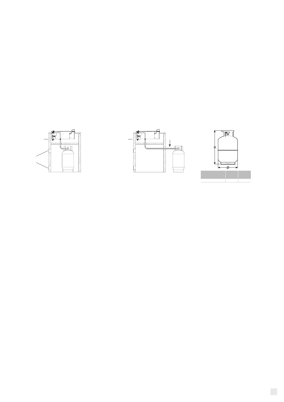
2.1 CYLINDER CONTAINER
If the LPG cylinder is positioned under the appliance, it must be insulated from the non-combustible panel.
The compartment must comply with requirements of the national rules in force, providing that there are ventilation openings on the top and the
bottom of the compartment, each of which must provide a free surface of at least 200 Cm2 per cylinder housed.
See FIG.5, A2 and A3 - Ventilation opening of the cylinder container. (To perform if you place the cylinder under the appliance)
ATTENTION:
• Different types of cylinders can be used with this appliance, it is recommended to use LPG cylinders with the characteristics indicated in the
table.
• Always handle any gas cylinders with care.
• Always use the cylinder in vertical position.
• Place the cylinder in an accessible place in order to facilitate its opening or closing.
• Keep the cylinder away from any sources of heat.
2.2 VENTILATION OF THE PREMISES
• The appliance is not connected to an evacuation device for combustion products, therefore, it must be installed in places with permanent
ventilation, as provided for in National Rules in force. Inside the room where the appliance is installed, it is necessary that as much air as it is
required by the normal combustion of gas and the necessary ventilation of the room itself must be able to ow in. Intakes of air inow, protected
by grids, must be suitably sized in accordance with any National Rules and must be positioned in such a way as not to be obstructed, even
partially. Exhaust of combustion products must be brought to the outside through ues or by extractor hoods or electric fans, with a ow
rate which is such as to guarantee an hourly ventilation of at least 3 times the volume of the room (see National Rules in force). Intensive and
prolonged use of the appliance may require greater ventilation, for example, the opening of a window or more effective ventilation, e.g.: where
present, by increasing the level of mechanical ventilation. It should be noted that the air ow rate required for combustion is 2m
3
/h for every
KW of rated thermal ow (see the rating plate).
3 HOW TO CONNECT THE APPLIANCE
• This appliance can be set up to operate with LPG or natural gas. Please refer to “Charts of burners and nozzles characteristics” to know the
pressure of burners and proper size of nozzles. (See TAB.1)
• The feed pressure must observe the values reported in the table of paragraph “Types of gas and Home Countries”. (See TAB.2)
All the necessary adjustments for proper functioning and testing of the appliance are carried out in the factory.
• For proper functioning, please use a pressure regulator, connecting pipe and ttings in accordance with EN directives and connect the cylinder
in accordance with the requirements laid down by the rules in force.
• In order to install or replace the pipe (please check periodically the expiry date of the same), it is necessary to refer to the regulations in force.
3.1 OPERATION WITH BUTANE/PROPANE GAS (SEE TECHNICAL DATA SHEET)
• In order to connect the cylinder, use ttings and regulators provided for by the legislation in force only. The use of non-compliant products
could seriously endanger the safety of the appliance.
The appliance must be connected to the cylinder by means of:
• Pressure regulator with xed setting according to national regulations in force (operating pressure as reported in TAB.1)
• Flexible pipes according to national regulations in force, of a suitable length (max. 1.5 m).
They must be mounted without folds, twists and they must not make contact with the bottom of the appliance.
3.2 CONNECTION OF THE APPLIANCE TO THE GAS CYLINDER
• Check that the tap’s washer of the cylinder is not damaged.
• Connect the pressure regulator to the cylinder (1).
• Check that the taps of the appliance are in the closed position.
• Fasten the pipe (2) to the regulator (1) if not already fastened in accordance with regulations in force.
• Fasten the other end of the pipe (2) to the connection of the appliance, by inserting correctly the washer (4) between the connection of the
appliance (3) and the hose holder (5) by tightening the exible pipe with the clip (6).
FIG. 2
Sample cylinder positioned below the
non-ammable panel
BBQ ventilation holes
Grates or ventilation
holes 200 cm
2
MAX 1,50 mt
Example of the cylinder positioned
in the back
BBQ ventilation holes
MAX 1,50 mt
Max
(Kg)
H
(mm)
Ø
(mm)
5 500 270
 Loading...