EasyManuals Logo

Planmeca intra Installation Manual

Planmeca intra
68 pages
To Next Page IconTo Next Page
To Previous Page IconTo Previous Page
Page #33 background imageLoading...
Page #33 background image
Planmeca Intra X-ray unit 29
OTHER INSTALLATION ALTERNATIVES
Installation manual
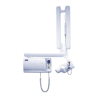
Attach the ceiling arm to the adapter with the upper mounting ring.
Move the lower mounting ring to the position shown on the figure below. With the locking screw
located on the lower mounting ring make a dent to the arm (the head of the locking screw differs
from the head of the normal attachment screws). This will lock the arm to the adapter. Replace the
locking screw with an attachment screw.
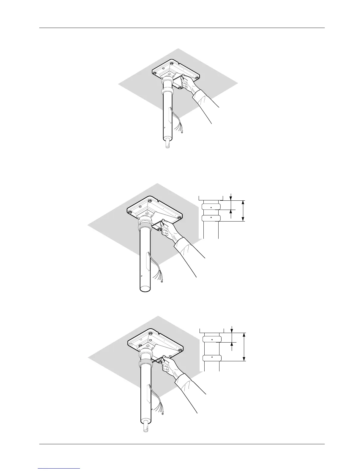
Move the lower mounting ring to the position shown on the figure below. Tighten all the mounting
rings’ screws firmly.
Ceil2.eps
30-32 mm
65 -
80 mm
Ceil3.eps
30-32 mm
100-105 mm
Ceil4.eps

Table of Contents

Other manuals for Planmeca intra

Questions and Answers:

Question and Answer IconNeed help?

Do you have a question about the Planmeca intra and is the answer not in the manual?

Planmeca intra Specifications

General IconGeneral
ManufacturerPlanmeca
ModelPlanmeca Intra
Frequency50/60 Hz
Tube Voltage60-70 kV
Tube Current7 mA
TypeDental X-ray Unit
Voltage100-240 V
WeightVaries depending on configuration; refer to specific model documentation

Related product manuals