Chapter E - C-ARM AND IMAGING ARM
E-76 ProMax X-ray unit with Dimax3
OTHER ADJUSTMENTS AND CALIBRATIONS
Technical Manual
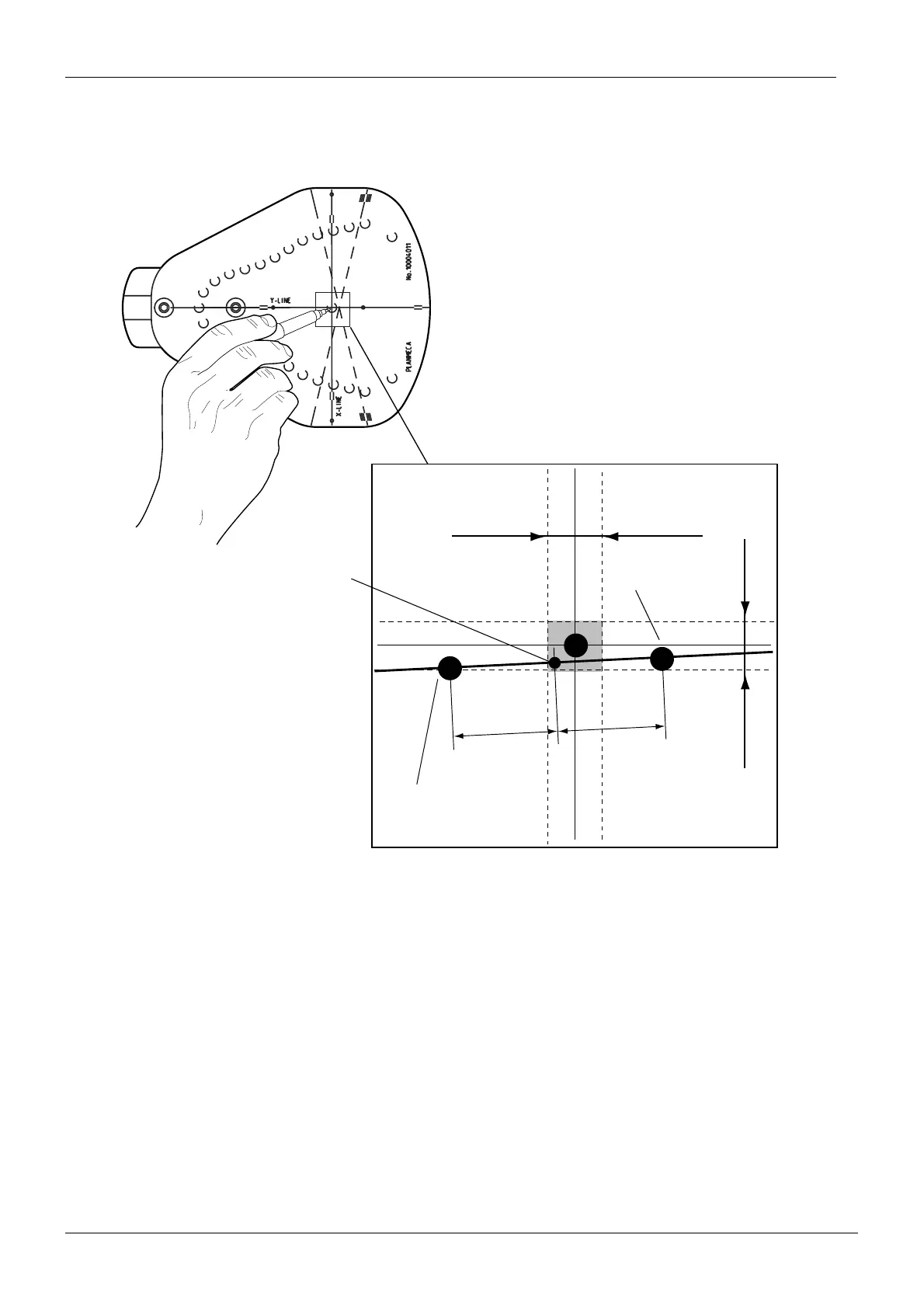
The real rotating centre is in the middle of the line between points a and b. This new crossing
point must be inside the ±1 mm limits from the ball phantom x-line and y-line crossing point.
If it is, adjust the lights to cross in this point.
Figure 118
In case the new crossing point is not inside the ±1 mm limits from the ball phantom x-line
and y-line crossing point, you must readjust the patient positioning mechanism, see section
1.12 “Additional adjustment method of the patient support alignment” on page E-52.
A
B
A=B
Y-LINE
X-LINE
2mm
2mm
PXR_Adj_laser5.eps
Point a
Point b
New crossing point

 Loading...


