Circuit breaker tripped/ Fuse
Blown
Re-set circuit breaker (push button in) situated on vehicle
or change fuse.
Check wiring inside handset or change module
Replace damaged or stretched springs.
Arm linkage has seized in
Press the down button whilst pulling lift out. Note: must
stand clear of platform.
Platform unfolds when not in use
Hose burst/ hydraulic leak
Check for leaking oil, replace all necessary components
Close tap and re-stow lift
Manual override tap left open/
down valve manual override
opened
Close “red” down valve tap and re-stow lift.
Re-set circuit breaker (push reset button in) situated near
to vehicle battery
Hose burst/ hydraulic leak
Check for leaking oil, replace necessary components
Low oil level in reservoir
drawing air into system
Top up reservoir with PLS BLUE hydraulic oil, 25mm from
top “max” (when lift is completely stowed)
Platform doors do not align
Replace damaged components.
Platform Knuckles not set
correctly
Adjust Platform Knuckles at platform pivot. Note: when
platform is down the Platform Knuckles must NOT be over
tensioned. i.e. can turn via finger pressure
See Platform Frame “Horizontal” Adjustment Procedure 7.3
See Platform Gates “Synchronizing” Procedure 7.4
Roll-off ramp not reaching floor.
NOTE. Keep fingers on DOWN
Button.
Spray all pivots and moving parts with ACF-50
Land the lift on a more suitable surface
Adjust stowage adjustment screws at base of platform to
set level position.
Bridging plate not dropping to
base plate
Lift not raised to max up
position
Power lift UP fully to floor height
Mechanism requires adjusting
Re-set and test bridge plate mechanism
Replace damaged components
Adjust stowage adjustment screws at base of platform to
set level position
See Platform Frame “Horizontal” Adjustment Procedure 7.3
See Platform Gates “Synchronizing” Procedure 7.4
Activation spring has lost
tension
Bridge plate hinge has jammed
Loosen and re-lubricate/ replace parts as necessary.
Bridging plate not returning to
vertical position
Mechanism has stuck in down
position
Re-set, lubricate and test bridge plate mechanism
Gas strut has lost pressure
Replace parts as necessary.
12.1 Troubleshooting Instructions Access™ EA & Access™ EAB
Diagrams
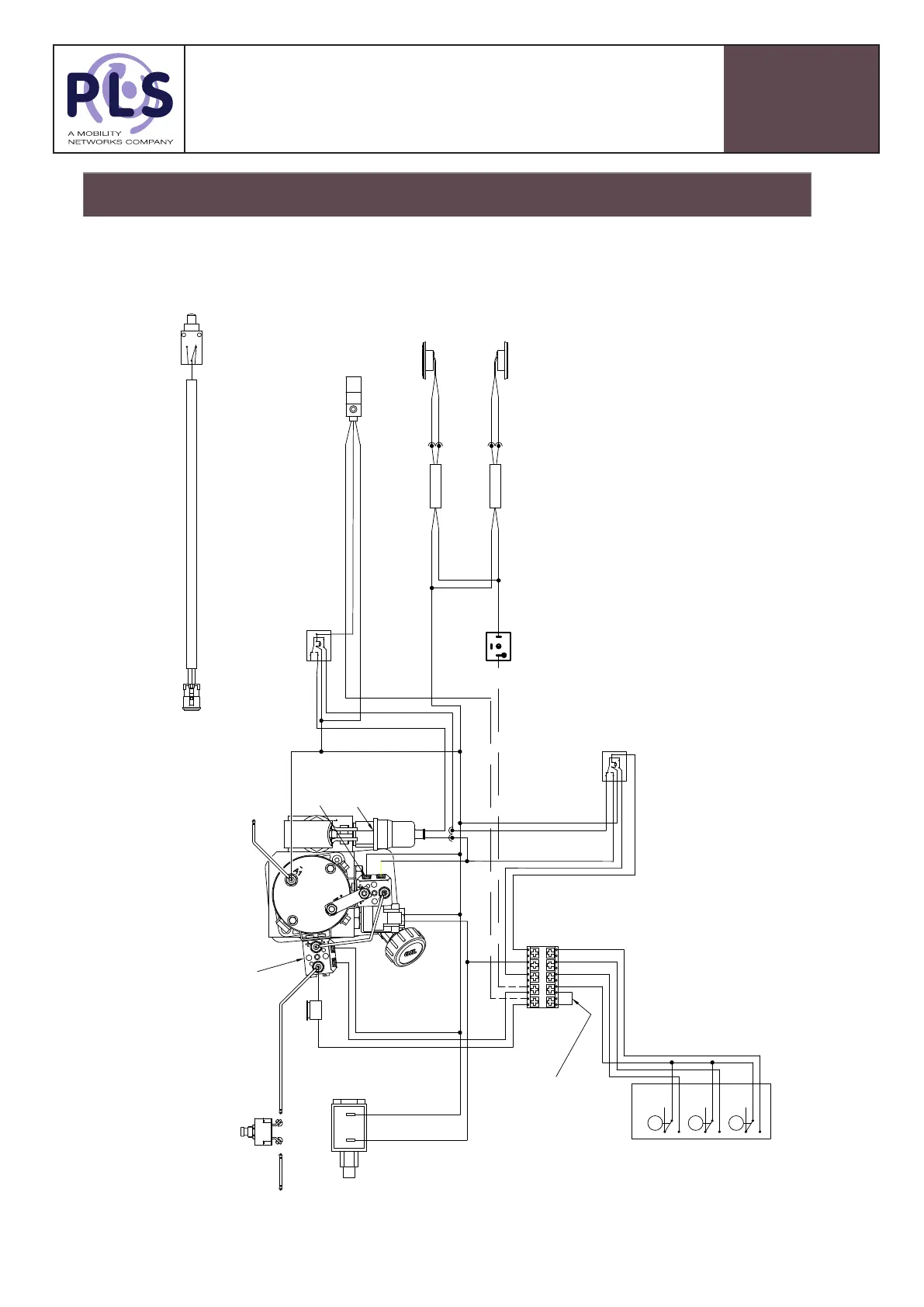
13.1 Wiring Diagram - Power Pack - 3 Options Access™ EA & Access™ EAB
Wiring Diagram- “Standard”
13.1 Wiring Diagram- Power Pack- 3 Options Access™ EA & Access™ EAB
SIDE LED LH
(OPTIONAL)
SIDE LED RH
(OPTIONAL)
DOWN=BLUE
STOW=YELLOW
UP
DOWN
STOW
3 BUTTON HANDSET
NC
COM
NO
NC
COM
NO
NC
COM
NO
1
2
RED
BLACK
2
1
1
2
RED
BLACK
2
1
STOP SENSOR
(OPTIONAL LOW PRESSURE
LIFTS)
FLASHER RELAY
(OPTIONAL)
UP=BROWN
LIVE=BLACK
BK
BN
YE
BL
RD
STOP RELAY
(OPTIONAL LOW PRESSURE
LIFTS)
STOW RELAY
SECONDARY DOWN VALVE
(OPTIONAL)
FUSE
10A
16mm
NEGATIVE
BATTERY CABLE
STARTER
SOLENOID
PRESSURE
SWITCH
ISOLATION SOLENOID
16mm
POSITIVE
BATTERY CABLE
12-24VDC
REMOVE LINK DURING INSTALLATION
BEFORE FITTING CAB/ DOOR SWITCH.
BN
RD
BL
BN
YE
BK
P
YE/RD
YE
BN
BN
BL
RD
BL/WH
BK
BN
BL
STOW WARNING SWITCH (BACK OF BOX)
THIS MICRO SWITCH IS USED TO SIGNAL WHEN THE LIFT IS
IN & OUT OF STOW. IT CAN BE USED TO SIGNAL A
WARNING LIGHT OR BUZZER ON THE DASHBOARD.
IT SHOULD NOT BE HARDWIRED TO THE VEHICLE BRAKES.
A
B
C
BU (NO)
BN/BK1 (COM)
BK2 (NC)
BLUE (NO)
BROWN (NO)
BLACK 1 (NC)
BLACK 2 (NC)
CIRCUIT BREAKER
12V=70A
24V=40A
2
1
S
U
D
S
C
13
 Loading...