_____________________________________________________ ________
11
Mastering the Art of Soldering www.plusivo.com
20 μA
±(1.5% + 3)
0.01 μA
200 μA 0.1 μA
10 A ±(2.0% + 5) 10 mA
Maximum input current: 10 A (not more than 10 seconds)
Overload protection: 0.2 A / 250 V fuse (10A range is without insurance)
Resistance
±(0.8% + 3)
20 kΩ 10 Ω
200 kΩ 100 Ω
2 MΩ ±(1.0% + 15) 1 kΩ
Overload protection: 250 V DC and AC peak
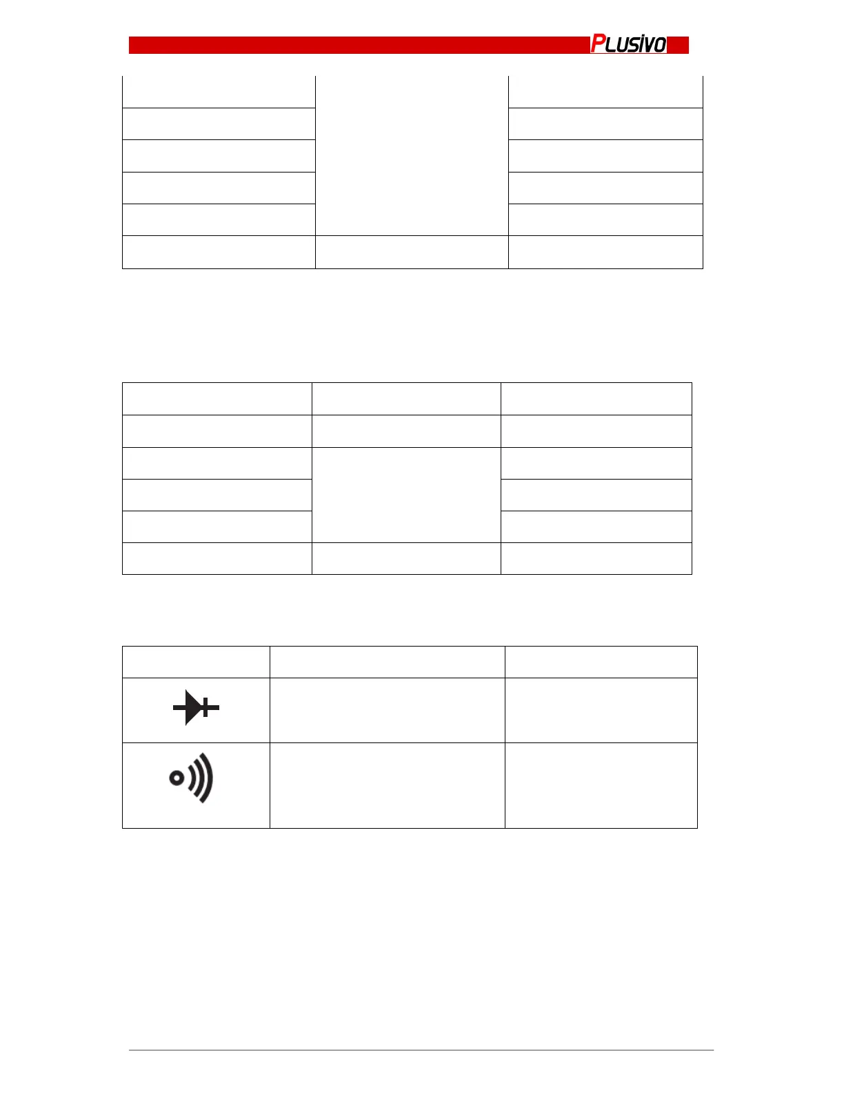
Diode and ON/OFF Test
Range Display Test Conditions
The diode forward voltage
DC current is about 1 mA
Reverse voltage: 3 V
Test Resistance smaller than (70
±20) Ω
Circuit starting voltage:
about 3V
Overload Protection: 250 V DC or AC peak
DC voltage measurement
1. Insert the black wire to "COM" and the red wire to the "V/Ω" port;
2. Put the range switch to the corresponding DCV range and then put the test probes to the
source to be measured. The polarity will be shown on the display.