Do you have a question about the PMA KS 800 and is the answer not in the manual?
Details electromagnetic compatibility standards and recommendations for the unit.
Lists the different versions of the KS 800 controller based on communication interface.
Provides guidance on how to mount the KS 800 unit on a standard rail.
Explains the procedure for safely removing the KS 800 unit from its mounting.
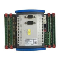
Describes the available terminal types and their connecting capacities.
Details the connectors used for connecting to fieldbus systems.
Illustrates the galvanic isolation between different blocks of the KS 800.
Specifies the required supply voltage range and load calculations.
Details the required fuse rating and protection for the unit.
Covers configuration for thermocouple, resistance thermometer, and voltage inputs.
Describes connecting DC voltages up to 100 mV as input signals.
Explains connection of Pt 100 sensors in 2 or 3-wire circuits.
Covers requirements for screening connecting cables for EMC compliance.
Details how to measure and monitor heating current and related alarms.
Provides visual examples for connecting various input types.
Describes the configuration and function of the four digital inputs.
Explains the use of digital I/O for system supervision or forcing.
Details controller output functions depending on configuration type.
Explains the current and voltage outputs for continuous control.
Describes the three alarm outputs and their configurations.
Details the 10V constant voltage source and auxiliary relays.
Shows detailed circuit diagrams for inputs and outputs.
Provides a comprehensive wiring diagram for the KS 800 unit.
Shows wiring for the 10V constant voltage option.
Explains the PC interface for configuration and control.
Covers Profibus, CANbus, RS422/485, and DeviceNet connectivity.
Details the specific adapter for DeviceNet communication.
Explains address and baudrate adjustment for the COM2 interface.
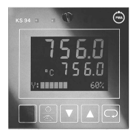
Indicates the status of outputs 1-16 and digital inputs 13-16.
Explains the function of power, communication, and general alarm LEDs.
Details the meaning of AL1-AL3 LEDs for specific alarm functions.
Provides instructions for cleaning the unit.
Offers guidance for diagnosing and resolving common issues.
Outlines the procedure for safely shutting down the unit.
Lists contact information for technical support and sales.
Specifies copper wire type and terminal screw torque for UL compliance.
| Brand | PMA |
|---|---|
| Model | KS 800 |
| Category | Temperature Controller |
| Language | English |