
C
christina16Aug 3, 2025
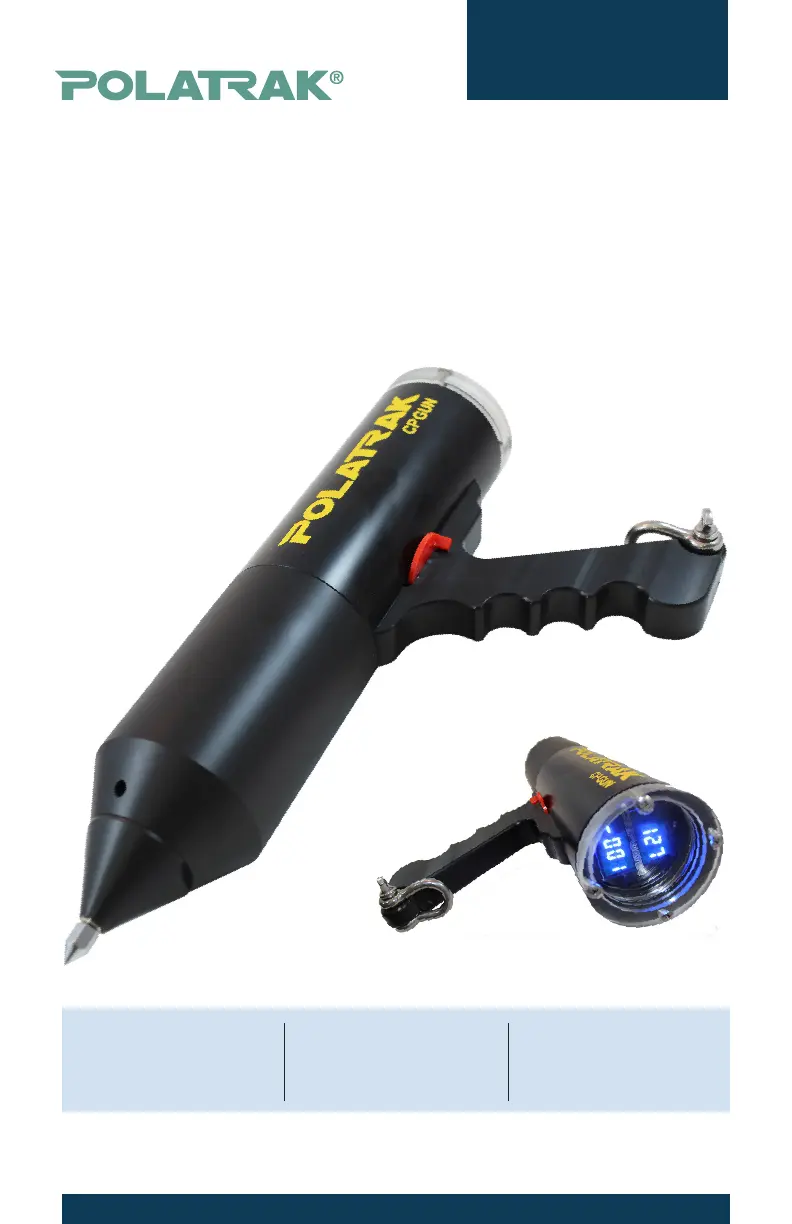
What to do if LED readouts are blank on Polatrak Measuring Instruments?
- SSpencer KentAug 3, 2025
If the LED readouts are blank, verify the switch position (Forward: on, Rear: off). Also, check if the batteries are dead and replace them if necessary. In case the pressure housing is flooded, use a backup unit and return the faulty unit to Polatrak.