Do you have a question about the Polon-Alfa POLON 4000 and is the answer not in the manual?
Overview of the manual's scope and purpose.
Defines the intended use and operating conditions for the POLON 4900 panel.
Details measures to prevent electric shock during use.
Outlines safe practices for installing the control panel and its components.
Specifies requirements for authorized personnel to conduct repairs and maintenance.
Provides instructions and considerations for replacing fuses correctly.
Explains key terms and concepts used throughout the documentation.
Presents a table detailing the items included in the POLON 4900 control panel package.
Lists key technical specifications like voltage, current, resistance, and capacity.
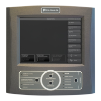
Provides a general overview of the control panel's physical design and features.
Illustrates the layout and placement of internal modules within the control panel.
Details the user interface elements on the control panel door for operation and status indication.
Describes specific buttons, indicators, and their functions on the operator console.
Explains the functionality of the keypad and associated buttons for input and navigation.
Details the components and functions of the operator console for system interaction.
Explains the role and features of the central controller module in managing panel operations.
Describes indicators and switches on the PSC-49 module for status and configuration.
Covers the function and specifications of line modules for connecting detection devices.
Details the capabilities of modules providing programmable outputs and inputs for system control.
Explains the configuration and types of PK relay and LS signal outputs.
Describes the interface module for connecting external devices like PCs and terminals.
Explains the power sources, including AC mains and battery backup, and their functions.
Differentiates between A-type (loop-shaped) and B-type (radial) detection line configurations.
Outlines methods for assigning unique numbers to addressable elements in the system.
Describes the process of automatically assigning numbers to elements based on their location.
Explains how to pre-declare elements for automated numbering and verification.
Details the procedure for manually assigning numbers to addressable elements.
Provides recommendations for designing reliable addressable detection line layouts.
Explains how to group addressable elements into logical zones for alarm management.
Covers the process of defining and assigning properties to addressable elements in the system.
Details how to configure alarm variants and messages for specific zones.
Describes the declaration and configuration of EKS elements for controlling external devices.
Explains the declaration and programming of EWS elements for controlling multiple outputs.
Details the declaration and configuration of EWK elements for monitoring inputs.
Covers the declaration and programming of SAL devices for acoustic alarms.
Explains the different alarm states, stages, and their indications.
Describes preliminary, 1st stage, and 2nd stage alarms and their visual/audible signals.
Details the behavior of a single-stage alarm variant, suitable for high-risk zones.
Explains the two-stage alarm process with time delays for personnel reaction.
Describes how the control panel detects and signals various types of faults.
Categorizes faults into system, module, line, and power supply faults.
Outlines the procedures for testing various system components and functionalities.
Explains how to disable and re-enable system elements like zones and devices.
Details the process for disabling specific devices or entire zones.
Describes the storage and retrieval of system events and alarms.
Details the MSI-48 module's role in connecting control panels into a network.
Explains how control panels function within a network environment.
Describes the mode where operations relate only to the local control panel.
Explains the mode for viewing the status of the entire common detection area.
Covers accessing and controlling other panels in the network remotely.
Provides guidelines on selecting an appropriate and accessible location for panel installation.
Details the procedure for connecting the main power supply and battery backup.
Explains how to connect detection lines and signalling circuits to the control panel.
Lists and describes the terminal blocks for panel inputs and outputs.
Outlines essential rules for ensuring the control panel's reliable and safe operation.
Specifies the requirements for regular inspections and maintenance activities.
Describes the packaging materials and items included with the control panel.
Provides guidelines for safe transportation of the control panel.
Outlines the recommended conditions for storing the control panel.
| Power Supply | 230V AC, 50Hz |
|---|---|
| Protection Class | IP30 |
| Number of Zones | 4 |
| Event Log | Yes |
| Communication Interface | RS-485 |
| Relative Humidity | Up to 95% (non-condensing) |
| Alarm Sound Level | 85dB at 1m |
| Type | Conventional Fire Alarm Control Panel |
| Battery Backup | Yes, 12V/7Ah |