Type WE6s32
WK 420 970 05.2018
- 12 -
a
aa
a
b
bb
b
b
bb
ba
aa
a
0
00
0
P
PP
P
T
TT
T
B
BB
B
A
AA
A
1740,5
310,75
32,5
O
45
73
O
5,3 - 4 holes
O
9,4 - 4 counterbores
49
3172,5
249
23
42
1
2
3 4
5
6
=
=
idle movement
working motion
working motion
idle movement
11
1
6
°
1
6
°
=
=
~150
O
16
18,5
O
11
H
70,5
45
O
20
8
~ 6
unlocked position
locked position
7
3
33
3-p
-p-p
-po
oo
os
ss
si
ii
it
tt
ti
ii
io
oo
on
nn
n
v
vv
vers
ersers
ersi
ii
io
oo
on
nn
ns
ss
s
W
W W
WE
EE
E6
66
6
.../...
HF
HF HF
HF Z
ZZ
Z4
44
4
...
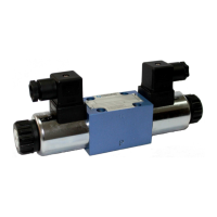
OVERALL AND CONNECTION DIMENSIONS
49 2,5
supply voltage
D
D D
DC
CC
C
12V
12V12V
12V
,
24V
24V24V
24V
,
110V
110V110V
110V
86
93
dimension
H
H H
H
plug-in connector type
ISO 4400
ISO 4400ISO 4400
ISO 4400 (DIN 43650 - A)
supply voltage
AC
AC AC
AC
110V
110V110V
110V
,
220V
220V220V
220V,
,,
, 230V
230V230V
230V
plug-in connector type
ISO 4400
ISO 4400 ISO 4400
ISO 4400 (DIN 43650 - A)
with rectifie
with rectifie with rectifie
with rectifie r
rr
r
Opt
OptOpt
Opti
ii
io
oo
on
n n
n o
oo
of co
f cof co
f con
nn
nnect
nectnect
necti
ii
io
oo
on
nn
n
...
Z
ZZ
Z4...
4...4...
4...
(
I
II
IS
SS
SO
O O
O 4
44
44
44
40
00
00
00
0
)
1 - Solenoid on side
a
aa
a
2 - Solenoid on side
b
bb
b
3 - Plug-in connector on side
a
aa
a
- type
ISO 4400
ISO 4400ISO 4400
ISO 4400 (DIN 43650 - A)
4 - Plug-in connector on side
b
bb
b
- type
ISO 4400
ISO 4400ISO 4400
ISO 4400 (DIN 43650 - A)
5 - O-ring
9,25 x 1,78
9,25 x 1,789,25 x 1,78
9,25 x 1,78
- pcs 4/set (
P
PP
P
,
T
TT
T
,
A
AA
A
,
B
BB
B
)
6 - Directional spool valve dimension with
2
2 2
2 s
ss
solen
olenolen
olenoids
oidsoids
oids
on side
a
aa
a
,
b
bb
b
:
3-po
3-po3-po
3-pos
ss
siti
itiiti
ition
onon
on springs centered
springs centered springs centered
springs centered
version WE6.../
...
HF
HFHF
HF
... (spool diagrams:
E
EE
E
,
F
FF
F
,
G
GG
G
,
H
HH
H
,
J
JJ
J
,
L
LL
L
,
M
MM
M
,
P
PP
P
,
U
UU
U
,
W
WW
W
- according to page 5
7 - Manual control lever
8 - Manual control lever lock sleeve
NOTES
NOTESNOTES
NOTES:
• versions WE6.../...H
HH
HF
FF
F... with other electrical connections,
see page 17
• porting pattern and requirements of surface state of the
subplate - as in version WE6.../...Z4
Z4Z4
Z4..., see page 7
NO
NONO
NOT
TT
TE
EE
ES:
S:S:
S:
The valve is switched by the manual control lever - item 7, return
of the lever to the initial (neutral) state occurs automatically. In
order for the lever - item 7 to remain in switched position, one
should move the lock sleeve - item 8 to the lower position until it
stops.
After switching the valve by using the solenoid - item 1or 2, the
lever - item 7 remains inactive.
 Loading...