Type WE6s32
WK 420 970 05.2018
- 18 -
3,3 kg
2,7 kg
2,1 kg
R
R R
Ra
aa
ange
nge nge
nge o
oo
of s
f sf s
f supp
uppupp
upply
ly ly
ly v
vv
vo
oo
olt
ltlt
ltage f
age fage f
age for
or or
or s
ss
sw
ww
witc
itcitc
itch
hh
h 1
11
10
0 0
0 -
- -
- 3
33
30
00
0V
V V
V D
DD
DC
CC
C
s
ss
sw
ww
witc
itcitc
itch
h h
h w
ww
wit
itit
ith
h h
h M
MM
M1
11
12
22
2x
xx
x1 exter
1 exter1 exter
1 extern
nn
na
aa
al t
l tl t
l thre
hrehre
hread
adad
ad
;
ma
mama
male c
le cle c
le co
oo
on
nn
nnect
nectnect
necti
ii
io
oo
on
nn
n
;
4 c
4 c 4 c
4 co
oo
on
nn
ntact
tacttact
tacts
ss
s
(pins)
C
C C
Co
oo
on
nn
nnect
nectnect
necti
ii
io
oo
on
n n
n type of
type of type of
type of s
ss
sw
ww
witc
itcitc
itch
hh
h
M
MM
Ma
aa
ax
x x
x l
ll
lo
oo
oad c
ad cad c
ad curre
urreurre
urren
nn
nt
tt
t 2
22
20
00
00 mA
0 mA0 mA
0 mA
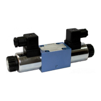
Weight of d
irectional valve
with 1 solenoid and 1 switch
Degree of pr
Degree of prDegree of pr
Degree of pr o
oo
otecti
tectitecti
tectio
oo
on
nn
n I
I I
IP
P P
P 6
66
65
55
5
S
SS
Sw
ww
witc
itcitc
itch
h h
h type
typetype
type
PN
PN PN
PNP
P P
P i
ii
ind
ndnd
nduct
uctuct
ucti
ii
ive pr
ve prve pr
ve pro
oo
ox
xx
xim
imim
imity
ity ity
ity s
ss
sw
ww
witc
itcitc
itch
hh
h
with 2 solenoids and 1 switch
with 2 solenoids and 2 switches
+
+
3
1
4
3
1
2
10-30V DC
10-30V DC
_
_
200 mA
200 mA
2
4
1
3
switch
on side
b
bb
b
1
0
1
0
switch
on side
a
aa
a
switch type
S
SS
S1
11
1
switch
on side
b
bb
b
1
0
1
0
switch
on side
a
aa
a
0 50
50
switch type S2
S2S2
S2
a
a a
a
spool position [%]
b
bb
b
100
100
0 50
50
a spool position [%] b
100
100
pin 2
pin 2
pin 4
pin 4
position monitored
a
aa
a
and
b
bb
b
position monitored
0
00
0
switch
on side
b
bb
b
1
0
1
0
switch
on side
a
aa
a
switch
on side
b
bb
b
1
0
1
0
switch
on side
a
aa
a
0 50
50
a
a a
a
spool position [%]
b
bb
b
100
100
0 50
50
a
a a
a
spool position [%]
b
bb
b
100
100
switch type
S
SS
S1
11
1
switch type S2
S2S2
S2
pin 2
pin 2
pin 4
pin 4
A
B
P
T
a
aa
a
b
bb
b
0
00
0
0
00
0
- off neutral state on output coctact
1
11
1
- on state on uotput contact
i
ii
in
nn
nit
itit
iti
ii
ia
aa
al p
l pl p
l po
oo
os
ss
sit
itit
iti
ii
io
oo
on
n n
n o
oo
of i
f if i
f ind
ndnd
nduct
uctuct
ucti
ii
ive s
ve sve s
ve sw
ww
witc
itcitc
itch
h h
h type S depend
type S dependtype S depend
type S depend i
ii
ing
ng ng
ng o
oo
on
n n
n t
tt
the
he he
he sp
spsp
spo
oo
oo
oo
ol p
l pl p
l po
oo
os
ss
sit
itit
iti
ii
io
oo
on
nn
n
di
didi
diagr
agragr
agram f
am fam f
am for
oror
or
direct
directdirect
directi
ii
io
oo
on
nn
na
aa
al
l l
l v
vv
va
aa
al
ll
lve
veve
ve
3
33
3-p
-p-p
-po
oo
os
ss
sit
itit
iti
ii
io
oo
on
n n
n vers
versvers
versi
ii
io
oo
on
nn
n
D
DD
Di
ii
iagr
agragr
agram
amam
ams
s s
s o
oo
of electr
f electrf electr
f electric
icic
ica
aa
al c
l cl c
l co
oo
on
nn
nnect
nectnect
necti
ii
io
oo
on
n n
n o
oo
of i
f if i
f ind
ndnd
nduct
uctuct
ucti
ii
ive s
ve sve s
ve sw
ww
witc
itcitc
itch
h h
h type S
type Stype S
type S
type
S
SS
S1
11
1
type
S
SS
S2
22
2
contact allocation (pins of
switch connector)
D
DD
Di
ii
iagr
agragr
agram
amam
ams f
s fs f
s for d
or dor d
or direct
irectirect
irecti
ii
io
oo
on
nn
na
aa
al c
l cl c
l co
oo
on
nn
ntro
trotro
trol
l l
l v
vv
va
aa
al
ll
lves
ves ves
ves a
aa
and
nd nd
nd i
ii
in
nn
nit
itit
iti
ii
ia
aa
al p
l pl p
l po
oo
os
ss
sit
itit
iti
ii
io
oo
on
nn
ns
s s
s o
oo
of s
f sf s
f sw
ww
witc
itcitc
itche
hehe
hes
ss
s
ACCESSORIES
Spool position switch type S
Add
AddAdd
Addit
itit
iti
ii
io
oo
on
nn
na
aa
al tec
l tecl tec
l tech
hh
hn
nn
nic
icic
ica
aa
al d
l dl d
l dat
atat
ata
aa
a
 Loading...