Type WE6s32
WK 420 970 05.2018
- 7 -
WYMIARY GABARYTOWE I PRZYŁĄCZENIOWE
a
aa
a
b
bb
b
23
45
H
H
H
H
6
57
1
2
5
O
5,3 - 4 otw
O
9,4 - 4 pogł
42
3
4
15
8
7
9
P
PP
P
T
TT
T
B
BB
B
A
AA
A
154
154
32,5
45
O
40,5
17
73
218
8,7
31
0,75
wersj
wersjwersj
wersja
a a
a W
WW
WE
EE
E6...
6...6...
6.../...
/.../...
/...Z
ZZ
Z4...
4...4...
4...
(przyłącze elektryczne typ
I
II
IS
SS
SO
O O
O 4
44
44
44
40
00
00
00
0
)
2,549
supply voltage
D
D D
DC
CC
C
12V
12V12V
12V
,
24V
24V24V
24V
,
110V
110V110V
110V
86
93
dimension
H
H H
H
plug-in connector type
ISO 4400
ISO 4400ISO 4400
ISO 4400 (DIN 43650 - A)
supply voltage
AC
AC AC
AC
110V
110V110V
110V
,
220V
220V220V
220V,
,,
, 230V
230V230V
230V
plug-in connector type
ISO 4400
ISO 4400 ISO 4400
ISO 4400 (DIN 43650 - A)
with rectifie
with rectifie with rectifie
with rectifie r
rr
r
Opt
OptOpt
Opti
ii
io
oo
on
n n
n o
oo
of co
f cof co
f con
nn
nnect
nectnect
necti
ii
io
oo
on
nn
n
...
Z
ZZ
Z4...
4...4...
4...
(
I
II
IS
SS
SO
O O
O 4
44
44
44
40
00
00
00
0
)
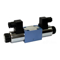
1 - Solenoid on side
a
aa
a
2 - Solenoid on side
b
bb
b
3 - Plug-in connector on side
a
aa
a - ISO
- ISO - ISO
- ISO 4400
44004400
4400
type
(DIN 43650 - A)
4 - Plug-in connector on side
b -
b -b -
b - ISO 4400
ISO 4400ISO 4400
ISO 4400
type
(DIN 43650 - A)
5 - Plug-in connector -
ISO 4400
ISO 4400ISO 4400
ISO 4400
type
(DIN 43650 - A)
with
rectifier
6 - O-ring
9,25 x 1,78
9,25 x 1,78 9,25 x 1,78
9,25 x 1,78
- pcs 4/set (
P
PP
P
,
T
TT
T
,
A
AA
A
,
B
BB
B
)
7 - Directional spool valve dimension with
2 s
2 s2 s
2 solen
olenolen
olenoids
oidsoids
oids
on side
a
aa
a
,
b
b b
b
:
•
3-po
3-po3-po
3-pos
ss
siti
itiiti
ition
onon
on springs centered
springs centered springs centered
springs centered
(spool diagrams:
E
EE
E
,
F
FF
F
,
G
GG
G
,
H
HH
H
,
J
JJ
J
,
L
LL
L
,
M
MM
M
,
P
PP
P
,
U
UU
U
,
W
WW
W
- according to page 5
•
2-pos
2-pos2-pos
2-positi
itiiti
ition
onon
on with
with with
without
outout
out return springs
return springs return springs
return springs
•
2-pos
2-pos2-pos
2-positi
itiiti
ition
onon
on with
with with
without
outout
out springs and wit
springs and wit springs and wit
springs and wit h detent
h detenth detent
h detent
(versions
WE6.../
O
OO
O
...; .../
O
OO
OF
FF
F
...
; spool diagrams:
A
A A
A
,
C
CC
C
,
D
D D
D
,
E
EE
EA
AA
A
,
GA
GAGA
GA
,
HA
HAHA
HA
,
JA
JAJA
JA
,
MA
MAMA
MA
,
E
EE
EB
BB
B
,
GB
GBGB
GB
,
H
HH
HB
BB
B
,
JB
JBJB
JB
,
MB
MBMB
MB
- acc. to pages 5, 6)
8 - Directional spool valve dimension with
1
1 1
1 s
ss
solen
olenolen
olenoid -
oid -oid -
oid -
on side
a
a a
a
•
2-pos
2-pos2-pos
2-positi
itiiti
ition
onon
on springs centered
springs centered springs centered
springs centered
(spool diagrams:
A
A A
A
,
C
CC
C
,
D
DD
D
,
D
DD
D1
11
1
,
E
EE
EA
AA
A
,
FA
FAFA
FA
,
GA
GAGA
GA
,
HA
HAHA
HA
,
JA
JAJA
JA
,
LA
LALA
LA
,
MA
MAMA
MA
,
PA
PAPA
PA
,
UA
UAUA
UA
,
W
WW
W
A
AA
A
- according to pages 5, 6)
9 - Directional spool valve dimension with
1
1 1
1 s
ss
solen
olenolen
olenoid -
oid -oid -
oid -
on side
b
b b
b
•
2-pos
2-pos2-pos
2-positi
itiiti
ition
onon
on springs centered
springs centered springs centered
springs centered
(spool diagrams
:
::
:
B
B B
B
,
Y
Y Y
Y
,
Y
Y Y
Y1
11
1
,
E
EE
EB
BB
B
,
FB
FBFB
FB
,
GB
GBGB
GB
,
H
HH
HB
BB
B
,
JB
JBJB
JB
,
LB
LBLB
LB
,
MB
MBMB
MB
,
P
PP
PB
BB
B
,
U
UU
U
B
BB
B
,
WB
WB WB
WB
- according to pages 4, 5
10 -
Porting pattern of the subplate surface compliant
with
I
II
IS
SS
SO
OO
O
4
44
44
44
40
00
01
11
1
standard;
designation
I
II
IS
SS
SO
OO
O
4
44
44
44
40
00
01
11
1
-
0
00
03
33
3
-02-0-94 (CETOP 03);
fixing screws
M5 x 50
M5 x 50 M5 x 50
M5 x 50 - 10
- 10- 10
- 10.9
.9.9
.9
in accordance with
P
PP
PN
NN
N -
- -
-
E
EE
EN
NN
N
I
II
IS
SS
SO
OO
O
4
44
47
77
76
66
6
2
22
2
- pcs 4/set; tightening torqu
e Md = 9 Nm
e Md = 9 Nme Md = 9 Nm
e Md = 9 Nm
11 - Subplate surface required
P
PP
P
T
TT
T
B
BB
BA
AA
A
5,95
16,25
26,55
0,75
10,3
19
27,8
40,5
10
73 (min)
17
M5 depth 10 - 4 holes
0,63
0,01/100
O
7,6 (max) - 4 holes (P, T, A, B)
11
45 (min)
32,5
31,75
 Loading...