PAGE 4 OF 4PRINTED IN USA
MKT. #8870002 - REV L
8/02
VSA-S
VAULT SOUND ALARM
SYSTEM
ORDERING INFORMATION
VSA-S Vault Sound Alarm System (Surface Mount) consists of:
Qty. Comp. No. Description
1 2000103 VSA - Amplifier with housing
1 5270080 Transformer 12V, 20VA
1 5130080 Battery 6V, 4 AH
2000008 PSM - Microphone (Surface Mount)
(45 ohm impedance)
1 2000041 PSM-T - Microphone with
Test Sounding Device
Additional Items Available:
Qty. Comp. No. Description
1 2000008 PSM - Microphone (Surface Mount)
1 2000034 PSM-F - Microphone (Flush Mount)
(Includes back box)
1 5090008 Back Box for PSM-F
1 2020121 PTU-B - Remote Test Unit
1 5090033 Back Box for PTU-B
1 2009103 VSA - Less housing/PCB only
1 2000106 APC - Accumulation Pulse Counter
*
2020130 HUB-M - Single Action hold up Button
*
2020132 HUB-T - Double Action hold up Button
Note:
*
- At least one of either hold up button is required in the vault
for U.L. installation.
APC SENSITIVITY ADJUSTMENT
1. Set the VSA sensitivity control to 0.
2. Set the APC pulse counter switch to the desired number (1 thru 9).
3. Install the APC and produce the minimum noise level which the
APC is to detect. Adjust the APC sensitivity such that the yellow
LED light blinks each time this noise is produced (disregard the red
alarm light at this time).
4. Unplug and remove the APC.
5. Produce the minimum noise level at which the VSA should alarm
and set the VSA sensitivity control such that the red alarm LED
comes on each time this noise is produced. This noise level should
be much more intense than that used to set the APC sensitivity.
6. Re-install the APC.
TESTING
Slowly pulse the noise used to adjust the APC sensitivity control until
the VSA indicates alarm (illuminated red LED) on the VSA unit. The
counter in the APC is now reset to 0.
Slowly pulse this noise again. When the number of pulses equals the
switch setting on the APC, the VSA will indicate alarm. This verifies
that both the VSA and APC are operating properly at the desired noise
level.
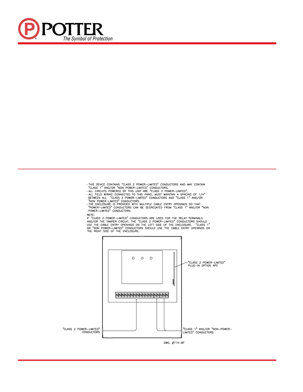
FIG. 7 SUGGESTED WIRE ROUTING
 Loading...