Italy Facility
Via S. Giorgio, 642
52028 Terranuova Bracciolini
Italy
+39 055 9195 1
Camarillo Facility
740 Calle Plano
Camarillo, California, 93012
United States
805-987-8741
Phoenix Facility
3201 East Harbour Drive
Phoenix, Arizona, 85034
United States
480-643-1700
Hong Kong Facility
Unit 1907-9, Tower 1, The
Gateway
25 Canton Road
Hong Kong S.A.R., China
http://www.power-one.com
Characteristics and technical data Check and increase of the radio signal
14.
15.
10. 13.
11.
12.
Service- Contact Details:
Australia +61 2 9735 3111 service.au@power-one.com
Benelux +32 2 206 0338 service.bx@power-one.com
China +8675529885888 service.cn@power-one.com
Eastern Europe +49 7641 95520 32 service.ee@power-one.com
France 00 800 00 28 76 72 service.fr@power-one.com
Singapore +65 6896 3363 service.sg@power-one.com
Spain 00 800 00 28 76 72 service.es@power-one.com
South east Asia service.sg@power-one.com
UK 0800 0232341 service.uk@power-one.com
USA +1 877-261-1374 service.us@power-one.com
Germany 0800 2200211 service.de@power-one.com
Greece 00 800 00 28 76 72 service.gr@power-one.com
India +65 6896 3363 service.in@power-one.com
Italy 00 800 00 28 76 72 service.it@power-one.com
Middle East 00 800 00 28 76 72
The display (composed by 2 lines with 16 character for each line) can be used for navigate the menu by using the UP, DOWN, ESC and ENTER buttons and allows for:
•Viewingtheoperatingstatusoftheinverterandstatisticsdata;•Viewingservicemessagesfortheuser;•Viewingalarmandfaultmessages;•Changingtheinvertersettings
Statistics
>
Output Voltage
....V
Frequency
....Hz
Temperature
....°C
Input Current
....A
Tot Output Power
....W
Total Energy
....kWh
Inverter Data
>
.. microinverter
SN: ...... >
Total Energy
.... Wh
Input Voltage
....V
Output Power
....W
Micro Release
.........
Model ID
MICROINVERTER
MAC Address
................
Output Current
....A
DSP Release
.........
View
Information >
PN
........
SN
..........
Firmware rel
>
Application FW
........
Bootloader FW
........
WiFi Firmware
........
RF Firmware
........
Inv/CDD DD/MM/YY
E... ON HH:MM:SS
Date
DD/MM/YY
Time
HH:MM:SS
Events
Alarm present >
Change
Settings >
Select Language
........
Set Date/Time
HH:MM DD/MM/YYYY
Set Timeout
0..10min/Off
Change Language
>
Set Date/Time
>
Display Timeout
>
Network
>
WiFi Network
xxxxxx
Tot Output Power
x.xx W
Total Energy
x.xx kWh
Alarm Status
xxxxxx
DD/MM/YY
HH:MM:SS
Web Server IP
..........
Secondary DNS
..........
MAC Address WiFi
................
WiFi Enabled
Yes >
Subnet Mask
...........
WiFi AutoConnect
Yes >
IP Gateway
...........
Web Server
Reset Password?
Primary DNS
..........
CDD Login
Reset Password?
CDD Admin
Reset Password?
Web Server
Are You Sure?
WiFi AutoConnect
No
WiFi AutoConnect
Yes
WiFi Enabled
No
WiFi Enabled
Yes
CDD Login
Are You Sure?
CDD Admin
Are You Sure?
Web Server
Done!
CDD Login
Done!
CDD Admin
Done!
Select Network
Ethernet/WiFi
DHCP Enabled
Yes/No
Web Server IP
........... >
Mask Address
........... >
IP Gateway
........... >
Primary DNS
........... >
Secondary DNS
........... >
Reset
Ground Fault ?
Reset
Are You Sure?
Reset
Done!
WiFi SSID:
xxxxxxxxxxxxxxxxxx
Structure of the display menu
During the normal operation of the
inverter GENERAL INFORMATION is
displayed.
By pressing any button during the normal operation (when the display
shows GENERAL INFORMATION) you gain access to the set up basic, and
information screens related to the CDD.
The 3 main menus allow access to
Statistics: displays statistics of the plant and of each MICRO inverter
View information: displays data related to the CDD and the list of errors or warnings
Change settings: Allows changing the settings of the CDD.
Press any button
Simultaneously press the UP and DOWN buttons for 3 se-
conds and then enter the password 0010
Once the acquisition of the MICRO inverters is completed it is possible to congure the remote monitoring of the plant on the Aurora Easy View web portal using
the Self Registration procedure (through the Power-One website).
To start the self-registration process go to https://register.auroravision.net/cdd?mac=AA:BB:CC:DD:EE:FF:GG:II (the page will be automatically opened if at
the end of the acquisistion process for the MICRO inverter you go to “CLICK HERE FOR REGISTER YOUR CDD XX:XX:XX:XX:XX:XX:XX:XX”).
The registration process is completed in three steps:
1. Enter your personal contact information and validate your email account.
You will be sent an email with a link to validate your email address. Open the e-mail and click on the link to continue the registration.
If you do not validate the account within 3 days the account will be invalidated and you will have to start over.
2. Provide dateils about your solar power site/home.
It is important to provide the installer’s name and contact information to help direct current and future homeowners to the installer for any future project and service needs.
Your site information defaults to the homeowner’s address but can updated to a dierent address for alternate locations such as the homeowner’s second home.
3. Link and validate your CDD to the solar power site.
• Make sure the CDD is connected to the internet.
• Enter the CDD’s RF MAC address (MAC RF) in the 8 display elds
• Click on the Validate button
If the CDD is validated, the logger and all congured MICRO inverters will be displayed
Click I’m Done to complete the registration process you will receive an e-mail conrming that the registration has been successfully completed.
The free Aurora Easy View Web Portal (easyview.auroravision.net) oers monitoring of the plant
remotely (via internet).
The portal is divided 3 main sections:
• The upper section has general information about the system
• In the middle is the graph of total production of energy for a period which can be set (from a
single day up to 365) and the output power of each MICRO inverter
• On the bottom are the Environmental Benets based on the total energy produced by the plant.
In addition to the monitoring, the portal oers automatic upgrade of the rmware installed in the
MICRO inverters and the CDD device. Every time new rmware is available, an e-mail asking for
conrmation to do the upgrade will be sent to the plant owner.
As well as being used for acquisition of the MICRO inverters by the CDD, the local Web Server makes it possible to monitor the whole system constantly, showing
the data for each individual inverter. The dierent menus are:
“Home” Menu
• The HOME page displays all the MICRO inverters with their serial numbers, instant energy output and
radio signal level. The table on the left shows the data for the whole system (energy output, total energy,
CO2 savings and system status.
“View” Menu
• Plant Info > plant data (name of the plant, place, country standard, etc...)
• RF Signals > a graph is displayed showing the radio signal strength for each inverter, and the messages sent.
“Cong” Menu
• Plant > setting of plant information (Name, place, etc) and grid standard of MICRO inverter
• Network>setting of the parameters related for network (DHCP) and to the Aurora Easy View (Sending
of data and events to the portal, automatic updates, etc). In case of automatic updates, the customer will
receive an e-mail alert if a new version of the rmware is available.
• Date/Time > Setting of CDD’s date and time
• CDD clone > Cloning of CDD in case of substitution. The new CDD ‘recognize’ AURORA MICRO inverters
previously installed in the system
• Ground Fault/Energy > Allows unlocking of an inverter which detected ground fault error, and resetting
the energy value of each MICRO inverter
• Change Pass> Allows changing the password for the advanced functions of the Local Web Portal (by default Username: Admin / Password: Admin)
“Events” Menu
• Accesses the list of events signaled by the MICRO inverters or by the CDD.
“Upgrade” Menu
• CDD Firmware > Allows for upgrade of the CDD rmware
• uP Firmware/Dsp Microinv > Allows for upgrade of the rmware of the microprocessor (uP) and /or the DSP inside the MICRO inverter
“Registration” Menu
• Accesses to the Self Registration procedure in the Aurora Easy View web Portal (it is necessary to be connected to internet).
“?” Menu (Help)
• Contacts for the Power-One Service in case assistance is needed.
Local Web Portal Self Registration procedureWeb Portal Aurora Easy View
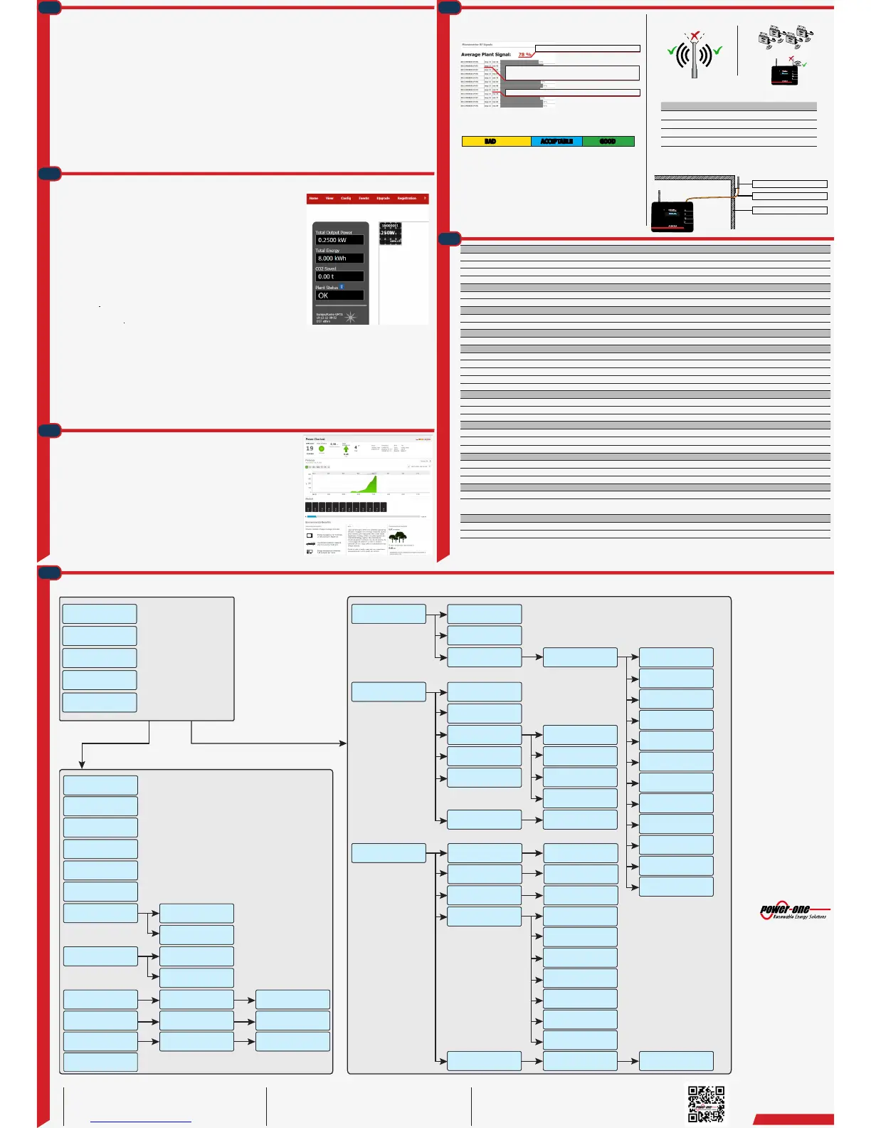
It should not be facing the MICRO inverters as shown in the pictures below:
2. Try a new location for the CDD taking account the signal decrease through
materials through which the radio signal has to pass:
Material Relative signal range reduction
Open Field Approximately 50 meters
Wood / Glass From 0 to 10%
Stone / Pressed cardboard From 10 to 40%
Reinforced concrete From 10 to 90%
Metal Up to 100 %
3. Install an extension cable for the antenna (CDD Antenna Extension Cable). the cable
allows the antenna to be installed at a distance over the obstacle for the radio signal.
The radio signal level between CDD and MICRO inverter can be checked throu-
gh the Local Web Portal. Inside the View Menu > RF signal (enter Username and
Password (Default Admin / Admin)
Medium signal level from MICRO inverter
Number of messages sent to the CDD in the last 15 minutes
MICRO inverters send a data packet every minute
Indicator of power of received signal
On the basis of medium signal level (after at least 20 minutes of acquisitions ) the
quality of radio communication can be considered:
0% 40% 70% 100%
BAD ACCEPTABLE GOOD
Good: no problem with communication
Acceptable: possible delays in data transfer and slower rmware updating.
Bad: Try a new position for the CDD installation or strenghtening the signal.
The radio signal level between CDD and MICRO inverter can be increased in
dierent ways:
1. Change the position of the antenna.
The antenna has deadzone at its end.
CDD
Power-one
CDD
Power-one
Radio Antenna
CDD Antenna Extension Cable
Radio signal obstacle
Communication To Inverter
Type Radio IEEE 802.15.4
Sample Rate 1 min
Max Distance (free space) 50 m ( can be extended with Power-One repeater)
Max number of devices 30
Communication To Modem/PC
Wireless Communication Wi-Fi IEEE 802.11 / 2.4GHz / 10 Mbps
Wired Communication Ethernet RJ45 10/100 Mbps
Connectivity
Wired ports 1x RJ45 Ethernet, 1x RS485, 1x Go-Go Relay
Compatibility RS-485, AURORA protocol
Features
Operation Integrated Web Server
Power Supply
Type External plug-in adapter
Adapter Input 100...240 Vac ; 50/60 Hz
Adapter Output 5 Vdc - 1 A
Power Consumption typical 2,5W/ max. 5W
Battery 3Vdc, replaceable
Environmental
IP Degree IP20 / NEMA 1
Ambient Temperature -20…+55 °C / -4. . . 131°F
Relative Humidity <90% non condensing
Physical
Dimensions (H/W/D) 150x180x25 mm /5.9x7x1” (not extended antenna)
Weight 0.6 kg / 1.32 lbs
Mounting Wall mounting (screws provided)
Interface
Display 16 Characters x 2 lines OLED
Display Language IT-EN-FR-DE-ES
LED Bicolor (red and green)
Safety
Marking CE, cCSAus, FCC
Safety and EMC Standards EN 62311; EN 60950-1; EN 301489-1 V1.8.1;EN 301489-17 V2.1.1; EN 55022; EN 55024; FCC Part 15 Class B /
Class C ; RTTE 1999/5/EC
Accessories
Antenna extension cable Optional
Plug-in power adapter Included
Remark. Features not specifically listed in the current data sheet are not included in the product
 Loading...