Do you have a question about the Powermate LiftGate LV-7 and is the answer not in the manual?
Swing LiftGate out, engage lock pin, extend unit, turn off power, and remove guard screws.
Remove bearing retainer screws and shim between retainer and inner frame.
Loosen set screws in ballnut locknut and unthread it from the ballnut.
Remove roll pin from lower coupling using a punch, supporting the drive screw.
Hand-turn ballnut to bottom, place arbor tool, and wind ballnut onto the arbor.
Transfer new ballnut to arbor, slide onto drive screw, wind it on, and remove arbor.
Re-install drive screw components in order, including the roll pin.
Dry fit components, tighten locknut, mark position, unthread, and grind a flat spot.
Re-install ballnut, washer, bracket, and locknut, applying grease and tightening set screws.
Guide drive screw assembly, attach to motor, insert shim, and install bearing retainer screws.
Align holes in outer frame, attach frame to bracket with screws, and test operation.
Insert screw guard, push inwards, align holes, and install screws.
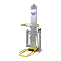
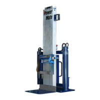
The PowerMate LV-7 is a specialized stair-climbing hand truck, also referred to as a LiftGate, designed for the safe and efficient transport of heavy loads up and down stairs. Its primary function is to assist users in moving items that would otherwise be difficult or dangerous to handle manually, thereby reducing the risk of injury and improving operational efficiency. The device utilizes a screw assembly system to facilitate its stair-climbing capabilities, allowing for controlled ascent and descent.
The PowerMate LV-7 operates by extending and retracting a screw assembly, which in turn manipulates the position of the toeplate and the overall frame relative to the ground or stair treads. This allows the unit to "walk" up or down stairs, maintaining stability and control throughout the process. The LiftGate functionality implies that the device can also be used to lift and lower items, potentially for loading onto vehicles or elevated surfaces. The unit is equipped with a main arm lock pin to secure its position when extended from a vehicle, ensuring stability during loading and unloading operations. For safety, it includes a circuit breaker switch and a heavy-duty switch to control power and operation. The design emphasizes ease of use, with components like the screw guard and ballnut assembly being accessible for maintenance and replacement.
While specific load capacities and dimensions are not detailed in the provided manual, the focus on "heavy duty" components and the intricate screw assembly system suggest it is designed for substantial loads. The use of specific tools like a 7/16" wrench, 5/32" Allen key, and 3/16" punch for maintenance indicates precise engineering and the need for specialized tools for servicing. The ballnut replacement process, which is the subject of the manual, is estimated to take approximately ¼ - 1 hour, suggesting a relatively straightforward, albeit detailed, maintenance procedure. The manual references a "drive screw" and "ballnut," which are critical components of a ball screw mechanism, known for its high efficiency and precision in converting rotary motion to linear motion. This type of mechanism is ideal for applications requiring smooth, controlled movement under heavy loads, such as a stair climber. The "disc spring washer" mentioned in the assembly process is likely used to provide a preload to the ballnut assembly, reducing backlash and increasing stiffness, which is crucial for precise and stable operation.
The PowerMate LV-7 is designed for practical use in various environments where heavy lifting and stair negotiation are required. Its "Stair Climbing Hand Truck" designation highlights its core utility. The "LiftGate" aspect suggests it can also function as a mobile lifting platform, enhancing its versatility. The operational steps outlined in the manual, such as swinging the unit out of a vehicle, engaging the main arm lock pin, and extending the toeplate to the ground, indicate a typical workflow for deploying the device. The ability to extend the unit until the toeplate touches the ground simplifies the process of disengaging the outer frame from the screw assembly, making it easier to prepare for operation or maintenance. The inclusion of safety switches (circuit breaker and heavy-duty switch) underscores the importance of user safety during operation. The design allows for the machine to be run up and down to check for proper operation after maintenance, ensuring functionality before active use.
The provided manual is entirely dedicated to the "Ballnut Replacement Instructions," highlighting a key maintenance procedure for the PowerMate LV-7. This suggests that the ballnut is a wear component that may require periodic replacement to maintain optimal performance and safety. The detailed, step-by-step instructions, complete with visual aids, are a significant maintenance feature, enabling users or technicians to perform the replacement accurately.
Key maintenance steps include:
The emphasis on supporting the drive screw to prevent bending during maintenance underscores the precision and care required when handling these components. The use of shims for proper orientation and alignment is also critical for the smooth and efficient operation of the LiftGate. The contact information provided (toll-free number, telephone, fax, and email) indicates strong manufacturer support for maintenance and inquiries. The manual's serial number applicability ("For all serial numbers") suggests a standardized design across different production batches, simplifying maintenance instructions.
| Brand | Powermate |
|---|---|
| Model | LiftGate LV-7 |
| Category | Lifting Systems |
| Language | English |