EasyManua.ls Logo

PowerNet ADC4370 SERIES User Manual

PowerNet ADC4370 SERIES
10 pages
To Next Page IconTo Next Page
Page #1 background imageLoading...
Page #1 background image
Powernet reserves the right to change the specification without notice Created: JMa/TRä 07.06.2012/ Updated: 19.08.2015 HLi 437c5q
DATASHEET / USER MANUAL
ADC4370 SERIES
800W Battery Chargers and Power Supplies
Wide output adjustment range 0…144VDC
Analog control by external 0-5VDC voltage
Temp.comp charging, sense as on option
Power fail relay alarm
Master-Slave connection
Sales & R&D Martinkyntie 43, FI-01720 VANTAA, Tel. +358 10 2890 700
E-mail marketing@powernet.fi, service@powernet.fi
Internet www.powernet.fi
Analog control
modular connector
Master-Slave
connection
Microprocessor controlled charging curves for all kind of
batteries
Question and Answer IconNeed help?

Do you have a question about the PowerNet ADC4370 SERIES and is the answer not in the manual?

PowerNet ADC4370 SERIES Specifications

General IconGeneral
BrandPowerNet
ModelADC4370 SERIES
CategoryBattery Charger
LanguageEnglish

Summary

Trimmer Adjustable Power Supplies

Analog Controllable Models

Temperature Compensated Chargers

Power Fail Relay Alarm Models

Master-Slave Connection

Customised Versions

Technical Data Specifications

Installation and Operation

Mounting Options

Details on wall and DIN-rail mounting procedures for secure installation.

Operation and Connections

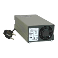
Steps for connecting and operating the power supply, including DC input and charging.

Output Adjustment and Protection

Covers output control, status LED, overcurrent protection, and parallel/series operation.

ADC4370 Feature Selection

Pin Configuration and Connectors

Alarm Relay Models

Analog Control Models

Analog Control Pin Configuration

Interface details for the analog control modular connector (J1).

Analog Card Control & Measurement

Explanation of voltage/current control and measurement via analog signals.

Connection Example & Tuning

Example connection using internal +5VDC and tuning instructions.

Temperature Compensation Models

Master-Slave Connection Guide

Bus Cable Connection

Details on connecting master and slave units using the digital bus for communication.

Programmed Voltages for Temp.Comp. Models

Changing Programmed Voltage

Checking Voltage Adjustment

Procedure to verify programmed voltage adjustment using status LED blinks.

Troubleshooting Hints

Guidance for common issues and troubleshooting steps if voltage adjustment fails.

Adjusting Voltage by Trimmer

Voltage Trimmer Adjustment

Steps for fine-tuning the output voltage using the internal calibration trimmer.