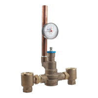
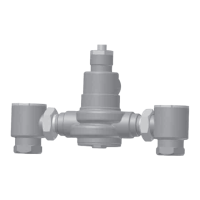
1. Installation should be in accordance with acceptable plumbing
practices. Flush all piping thoroughly before installation. Installation
and field adjustment are the responsibility of the installer.
2. Valves are to be installed as close to building inlet supply as
possible to prevent/minimize pressure fluctuations.
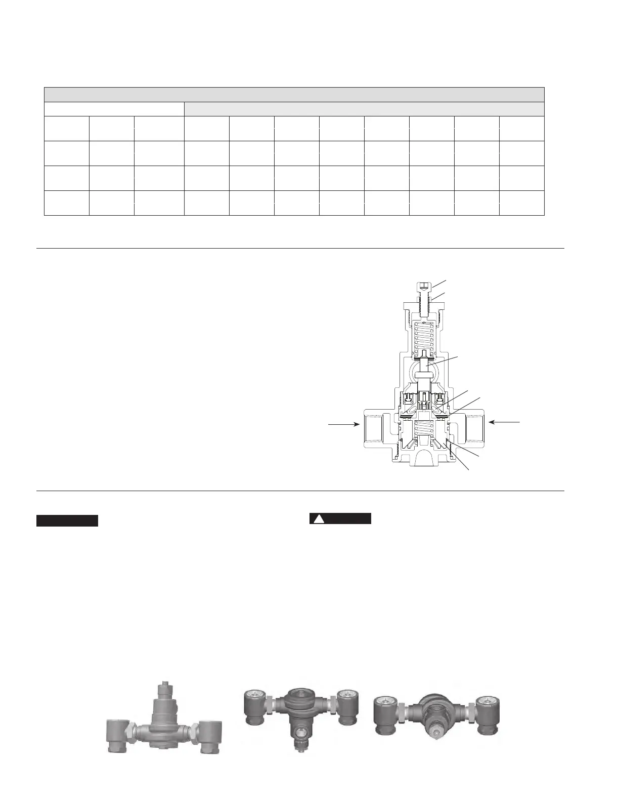
3. Valve body can be rotated to install in multiple positions due to
union inlets (see Figure 2). Make sure that union nuts are tightened
securely.
4. Connect inlets and outlet and check for leaks.
5. When the HydroGuard supplies tempered water to self-closing and/
or solenoid valves, provide a shock absorber (Powers Part No. 460-
353) on the discharge line.
6. Before use, check discharge temperature. Reset if
necessary.
OPERATION CHECK:
After HydroGuard is installed, make certain the supply stop valves and
strainers are free of debris, clean and ready for operation by disas-
sembling checkstops as shown in servicing.
Typical Flow
Hot and cold water supplies enter HydroGuard at indicated ports, (see
Figure 1) then flow past their respective seats. Next, hot and cold water
flow is directed to the mixing chamber where the thermostatic motor is
located.
Temperature Change
With a rise in discharge temperature due to pressure or temperature
fluctuation on the inlet, the actuator expands, decreasing flow of hot
water. The reverse occurs with a drop in discharge temperature.
Responses
Temperature adjustment screw moves the actuator to the desired
discharge temperature.
• Cold water supply failure – causes actuator to expand drastically
reducing the flow of hot water
*
.
• Hot water supply pressure failure – causes actuator to contract
drastically reducing the flow of cold water
*
.
*
When tested in accordance to conditions described in ASSE 1017.
Installation Instructions n
Operation n
Figure 2
Back Outlet
Front Outlet
Top Outlet
2
Figure 1
Temperature Adjustment Screw
Temperature Adjustment Locknut
Actuator
Mixing Chamber
Cold Water Seat
Hot Water Seat
Cold Water
Hot Water
Plunger
Flow Capacity at 50-50 mixed ratio
Pressure Drop Across Valve
Model
Min. Flow Min. Flow
C
V
5psi 10psi 20psi 30psi 45psi 60psi 70psi
Rate* to ASSE 1017
(34 kPa) (69 kPa) (138 kPa) (207 kPa) (310 kPa) (414 kPa) (517 kPa)
LFSH1432
0.5 gpm 1 gpm
8.54
19 gpm 27 gpm 38 gpm 47 gpm 57 gpm 66 gpm 71 gpm
1.89 lpm 4 lpm 72 lpm 102 lpm 144 lpm 178 lpm 216 lpm 250 lpm 269 lpm
LFSH1434
0.5 gpm 1 gpm
19.00
42 gpm 60 gpm 85 gpm 104 gpm 127 gpm 147 gpm 159 gpm
1.89 lpm 4 lpm 159 lpm 227 lpm 322 lpm 394 lpm 481 lpm 556 lpm 602 lpm
LFSH1435
0.5 gpm 5 gpm
30.00
67 gpm 95 gpm 134 gpm 164 gpm 201 gpm 232 gpm 251 gpm
1.89 lpm 19 lpm 254 lpm 360 lpm 507 lpm 621 lpm 761 lpm 878 lpm 950 lpm
* Minimum flow when HydroGuard is installed at or near hot water source with recirculated tempered water with continuously operating recirculating pump.
Capacity Table, presents the HydroGuard discharge capacity in gpm
and lpm for various pressure drops across the valves (the difference
Capacity n
between the lowest inlet pressure and the discharge pressure at the
HydroGuard.)
CAUTION
!
NOTICE
Distributed By: M&M Control Service, Inc.
www.mmcontrol.com/powershome.php
800-876-0036 847-356-0566


 To Next Page
 Loading...